
Method and device for locating pipeline blockage

A technology for pipelines and detection devices, which is applied in pipeline systems, mechanical equipment, gas/liquid distribution and storage, etc., and can solve problems affecting oil transportation tasks, heavy workload, and high operating costs

Inactive Publication Date: 2016-01-06
NORTHEAST GASOLINEEUM UNIV
View PDF5 Cites 2 Cited by
  • Summary
  • Abstract
  • Description
  • Claims
  • Application Information

AI Technical Summary

Problems solved by technology

There are disadvantages of heavy workload and high operating costs
In 1982, the Gela oil pipeline suffered a severe freezing accident. The drilling method was used to find the location of the freezing blockage. A total of 86 deep pits were excavated and 77 holes were drilled. The blocking time was as long as 5 months, which seriously affected the Completion of oil delivery tasks

Method used


Image

  • Method and device for locating pipeline blockage
  • Method and device for locating pipeline blockage
  • Method and device for locating pipeline blockage

Examples


Embodiment Construction

[0054] Below in conjunction with accompanying drawing, the present invention will be further described: this kind is made up of following steps to the localization method of pipeline blockage:

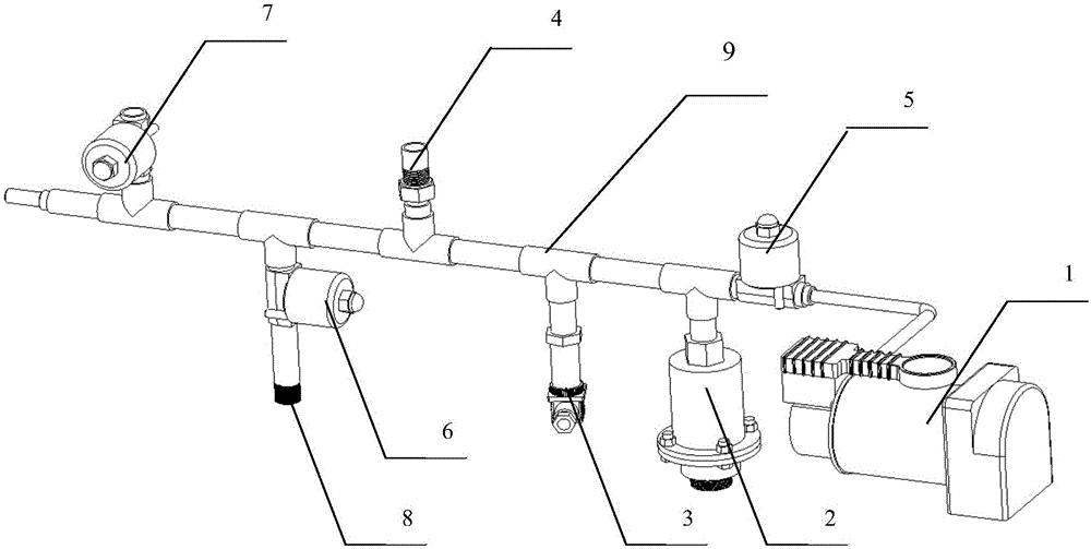
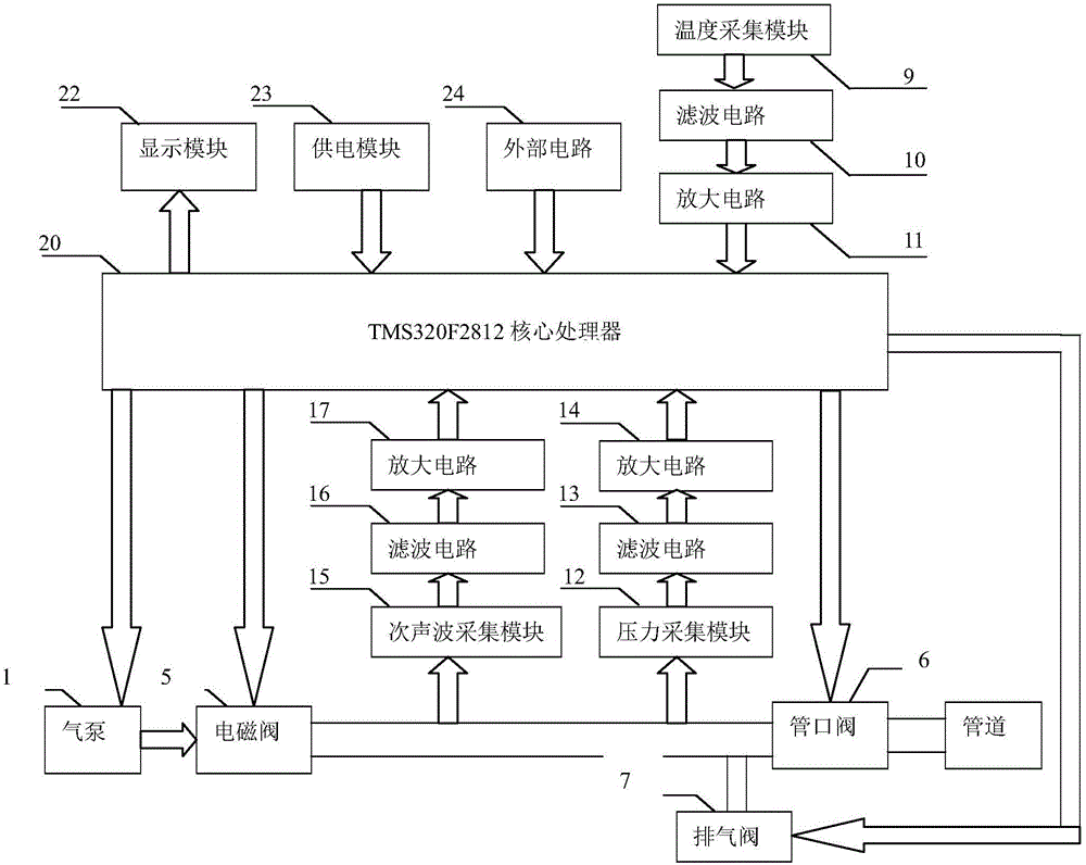
[0055] A detection device consisting of a core control board, a compressed air pump, an infrasonic sensor, a pressure sensor, a temperature sensor, a solenoid valve for controlling the release of sound waves, a nozzle valve, an exhaust valve and connecting pipes is installed on the pipeline to be tested;

[0056] Use the pressure sensor to collect the pressure value in the pipeline to be tested and the connecting pipeline. If the pressure value is greater than 0.2Mpa, control the exhaust valve in the detection device to open to release the gas in the pipeline;

[0057] Under the condition that the pressure meets the requirements, control the compressed air pump of the detection device to inflate automatically, the air pressure of each inflated air is 0.7MPa, and the gas volume is 35L pe...


PUM


Abstract

The invention provides a pipeline blockage positioning method and device, and mainly solves the problems that artificial pipeline blockage detection is difficult and the efficiency is low. The pipeline blockage positioning method is characterized by comprising steps as follows: a detection device consisting of a core control panel, a compressed air pump, a infrasonic wave sensor, a pressure sensor, a temperature sensor, an electromagnetic valve for controlling release of sonic waves, a nozzle valve, an exhaust valve and a connecting pipeline is mounted on a to-be-detected pipeline, and acquires the time difference delta t between the occurrence and echo of an infrasonic wave through an infrasonic wave collection module; after a pipeline blockage positioning calculation module acquires pressure and temperature in the pipeline, a sound velocity calculation module calculates the propagation velocity c of the infrasonic wave in the pipeline, the passing path of the infrasonic wave is shown as follows: L=c*delta t, and the distance between the pipeline blockage position and a pipe orifice is as follows: s=L / 2. The blockage position can be accurately positioned with the method, and the detection efficiency is effectively improved.

Description

technical field [0001] The invention relates to a method and a device for detecting pipeline blockage. Background technique [0002] Pipeline transportation is the main way of oil and gas transportation. Generally speaking, there are two situations that will require pigging operations. First, because the pipeline will be mixed with impurities such as soil when it is laid, it must be pigged when it is put into operation; second, due to the aging and corrosion of the pipeline material and the deposition of impurities contained in the natural gas , accumulation, resulting in the reduction of the flow area of ​​the pipeline, and even blockage. At the same time, these deposits will accelerate the internal corrosion of the pipeline, so pigging operations are required after the pipeline has been running for a period of time. Pigging balls are often used in pigging operations, and the balls may be stuck due to more sediment in the pipeline and cause blockage accidents. In the pri...

Claims


Application Information

Patent Timeline
Patent Type & Authority Patents(China)
IPC IPC(8): F17D5/00
Inventor 王秀芳姜建国姜春雷毕洪波阚玲玲张玉波
Owner NORTHEAST GASOLINEEUM UNIV
Learn More