Vehicle forward radar control method and forward radar system

A radar control and radar system technology is applied in the field of front radar systems to prevent collisions and ensure driving safety.

Inactive Publication Date: 2014-04-02
李铁葵
View PDF11 Cites 13 Cited by
  • Summary
  • Abstract
  • Description
  • Claims
  • Application Information

AI Technical Summary

Problems solved by technology

This method of controlling the work of the front radar by the brakes has the following problems. One, when the vehicle is waiting for a red light, if the driver always steps on the brake, the front radar will always work. When the distance between the rear car and the front car is at the front When the radar is within the detection range, the front radar will always remind the driver, which is an annoying thing for the driver; the second is in the road section that must be driven at a low speed, such as a road section in a community, or a narrow street, etc. When driving at low speed, the driver does not need to step on the brake most of the time. At this time, the front radar does not work, but when the vehicle is running at low speed, the road conditions are often more complicated, and the front radar needs to work to remind the driver to drive carefully. , at this time, the front radar did not play its due role; the third is that when the vehicle is driving at high speed, the front radar will also work when the vehicle needs to step on the brakes. For example, in the overtaking lane, the vehicle is close to the middle barrier of the road, it may happen), this reminder will cause unnecessary panic to the driver who is driving nervously on the high-speed section

Method used


Image

  • Vehicle forward radar control method and forward radar system
  • Vehicle forward radar control method and forward radar system

Examples


Embodiment Construction

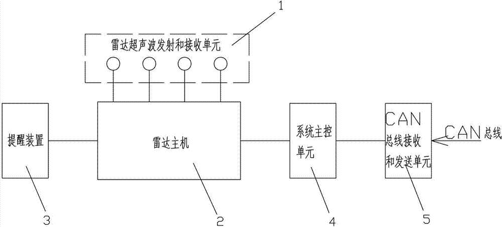
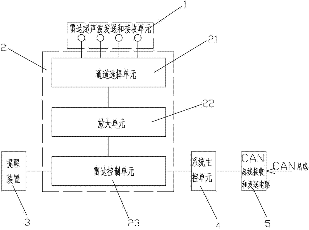
[0029] See figure 1 and figure 2 , figure 1 and figure 2 Disclosed is an improved front radar system, comprising a radar ultrasonic transmitting and receiving unit 1, a radar host 2, a reminder device 3, a system main control unit 4 and a CAN bus receiving and transmitting unit 5; the radar ultrasonic transmitting and receiving unit 1. The reminder device 3 and the system main control unit 4 are both connected with the radar host 2, and the CAN bus receiving and sending unit 4 is connected with the system main control unit 4; the system main control unit 4 works according to the following steps :

[0030] 1. Receive the vehicle signal from the CAN bus, the vehicle signal includes the ignition switch on signal, the reversing signal and the vehicle forward speed signal;

[0031] 2. According to the received signal and the following conditions are met, the front radar host 2 works;

[0032] A. When the ignition switch is connected to the circuit or the engine is started,...


PUM


Abstract

The invention discloses a vehicle forward radar control method and a forward radar system. The method comprises the following steps: (1) receiving vehicle signals from a CAN (controller area network) bus, wherein the vehicle signals comprise an ignition switch connection signal, a reversing signal and a vehicle forward driving speed signal; (2) enabling a system main control unit to work according to the received signals by meeting the conditions as follows: (A) when an ignition switch is turned on or an engine is started, a forward radar host works, and stops after preset working time is delayed, or (B) when a vehicle reverses, the forward radar host works, or (C) when the vehicle moves forward, the driving speed is bigger than 0 but not bigger than preset driving speed, and the forward radar host works. According to the vehicle forward radar control method and the forward radar system disclosed by the invention, the ignition switch is turned on or the engine is started, the forward radar host works, and thus, the car accident caused by the fact that a barrier exists in a blind area in front of the vehicle or the barrier is not discovered due to the carelessness of a driver can be avoided. When the vehicle reverses, the forward radar host works, the front of the vehicle can be prevented from collision; when the vehicle moves forward, and when the driving speed is bigger than 0 but not bigger than the preset driving speed, the forward radar host works, and thus, the driving safety of a road segment which is relatively complicated can be ensured.

Description

technical field [0001] The invention relates to a vehicle front radar control method and a front radar system. Background technique [0002] The existing vehicle front radar system generally includes a group of ultrasonic probes, a host and a voice prompt device. When the ultrasonic probe detects an obstacle within a predetermined range, the host computer judges the distance between the obstacle and the front of the vehicle, and emits a sound of a corresponding frequency to remind the driver to operate carefully. Whether the existing front radar system is working or not is controlled by the brakes. When the driver steps on the brakes, the front radar starts to work. After the brake is released, the front radar stops working after a certain time delay (usually 15 seconds). This method of controlling the work of the front radar by the brakes has the following problems. One, when the vehicle is waiting for a red light, if the driver always steps on the brake, the front radar ...

Claims


Application Information

Patent Timeline
Patent Type & Authority Applications(China)
IPC IPC(8): B60R21/013B60R11/00G01S15/93
Inventor 李铁葵
Owner 李铁葵
Why Eureka
Try Eureka