An ionic wind air purifier

An air purifier and ion wind technology, which is applied in the field of purifiers, can solve problems such as damage to insulation performance, aggravate tracking, corrosion, etc., and achieve the effects of improving yield, improving customer experience, and avoiding concerns

Active Publication Date: 2018-02-16
SUZHOU BEIANG TECH LTD
View PDF11 Cites 0 Cited by
  • Summary
  • Abstract
  • Description
  • Claims
  • Application Information

AI Technical Summary

Problems solved by technology

[0007] (3) Due to the working environment of the electrostatic precipitator, moist water vapor and dust pollutants attached to the fixed structure of 101 will aggravate the leakage tracking (the process in which the surface of the solid insulating material gradually forms a conductive path under the combined action of the electric field and the electrolyte) , induce corrosion and damage the insulation performance
[0008] The internal structure of the existing air purifier is very narrow, resulting in a very close distance between the positive electrode contact piece and the negative electrode contact piece, and this structure is very suitable for our ion wind air purifier (the pressure difference between the two poles of the ion wind air purifier is 4- 50,000 volts, which is much higher than the thousands of volts of ordinary electrostatic purifiers) very deadly
The existing technology does not provide a fundamentally feasible solution to the destructive effects of corona, arc, and tracking on metal terminals in terms of product structure design details. With the accumulation of product use time, the destructive accumulation reaches a certain level, resulting in product damage Unable to work normally, or make a "squeak" discharge sound when working, the effective working efficiency of the machine is extremely low, which affects the customer's experience of high-quality household appliances and creates concerns

Method used


Image

  • An ionic wind air purifier
  • An ionic wind air purifier
  • An ionic wind air purifier

Examples


Embodiment Construction

[0031] Objects, advantages and features of the present invention will be illustrated and explained by the following non-limiting description of preferred embodiments. These embodiments are only typical examples of applying the technical solutions of the present invention, and all technical solutions formed by adopting equivalent replacements or equivalent transformations fall within the protection scope of the present invention.

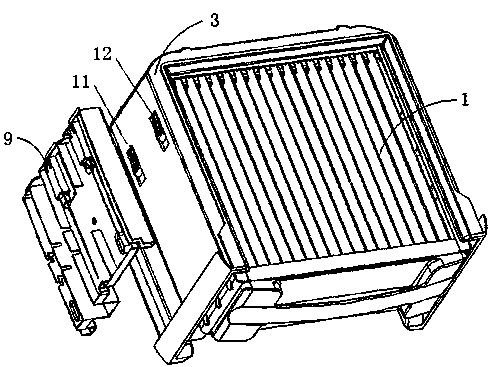
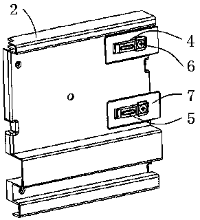
[0032] Such as figure 2 As shown, an ion wind air purifier includes an electrostatic precipitator 1 and a fixed structure 2, the electrostatic precipitator 1 is provided with an electrostatic precipitator protective cover 3, and the electrostatic precipitator protective cover 3 is designed The purpose is to prevent the electrostatic precipitator 1 from being impacted and in contact with rough and corrosive substances during use, and to better prolong the life of the electrostatic precipitator.

[0033] One side of the electrostatic precipitator is ...


PUM


Abstract

The invention discloses an ionic wind air purifier. The ionic wind air purifier comprises an electrostatic precipitator and a fixing structure. A positive contact terminal and a negative contact terminal are arranged on one side of the electrostatic precipitator. A positive contact chip and a negative contact chip corresponding to the positive contact terminal and the negative contact terminal are arranged on the side, facing the electrostatic precipitator, of the fixing structure. The positive contact chip and the negative contact chip are wrapped with high-voltage insulation sleeves correspondingly and fixed to the inner wall of the fixing structure in a spaced mode through the high-voltage insulation sleeves. According to the design scheme that the metal contact terminals of the ionic wind air purifier are improved, the problem that the ionic wind air purifier is damaged by coronas, arc discharge and tracking of the metal terminals is solved comprehensively and effectively, the situation that customers worry about the ionic wind air purifier due to discharge ignition sound is avoided, customer experience is effectively promoted, and the rate of qualified products is increased.

Description

technical field [0001] The invention relates to a purifier, in particular to an ion wind air purifier with a protection structure for preventing metal contact terminals from corona, electric arc and tracking. Background technique [0002] Dust collector (also known as dust collection box or collector) is the core technology module of the air purification device with the background of electrostatic dust collection technology, and its basic component is a pair of electrodes that generate an electric field. The extremely high voltage between the two plates (usually about 6000V) is transmitted to the plate of the dust collector by the booster circuit module, and a group of metal contact terminals is an important role in realizing the task of delivering the voltage. [0003] After investigation, the dust collector metal contact terminals of electrostatic dust collectors on the market generally adopt the assembly structure shown in the figure. Such as figure 1 It is a typical ar...

Claims


Application Information

Patent Timeline
Patent Type & Authority Patents(China)
IPC IPC(8): B03C3/04B03C3/34B03C3/70
CPCB03C3/04B03C3/34B03C3/70Y02A50/2351
Inventor 路尧远刘义刚
Owner SUZHOU BEIANG TECH LTD
Why Eureka
Try Eureka