Supercharge Your Innovation With Domain-Expert AI Agents!

Heat exchanger

A technology for heat exchangers and chambers, applied in the field of heat exchangers, can solve the problems of increasing the cost and design space of the inlet pipe, etc.

Inactive Publication Date: 2014-04-09
SAMSUNG ELECTRONICS CO LTD
View PDF8 Cites 7 Cited by
  • Summary
  • Abstract
  • Description
  • Claims
  • Application Information

AI Technical Summary

Problems solved by technology

[0004] However, since an increase in the number of inlet pipes increases cost design space, a structure using only one inlet pipe while improving refrigerant distribution has been studied

Method used


Image

  • Heat exchanger
  • Heat exchanger
  • Heat exchanger

Examples


Embodiment Construction

[0074] Now, embodiments of the present disclosure will be described in detail, examples of which are illustrated in the accompanying drawings, in which like reference numerals designate like elements throughout.

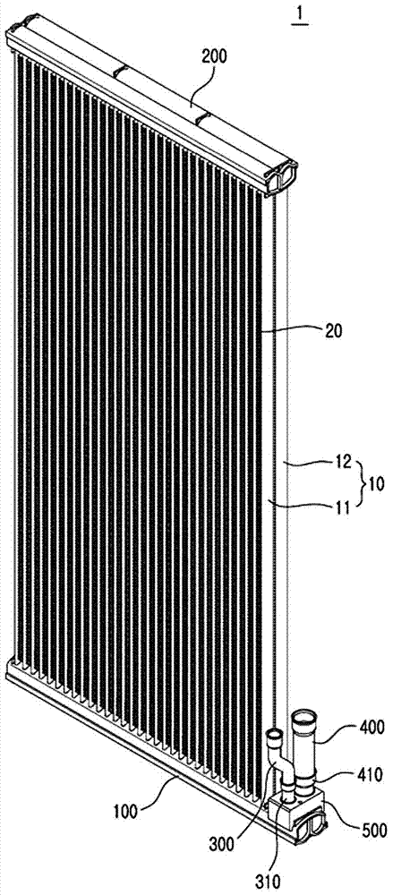
[0075] figure 1 is a perspective view showing the exterior of the heat exchanger according to the embodiment of the present disclosure.

[0076] refer to figure 1 , the heat exchanger 1 according to an embodiment of the present disclosure includes: a plurality of pipes 10 in which refrigerant flows and exchanges heat with air outside the heat exchanger; heat exchange fins 20 contacting the plurality of pipes 10, To increase the heat transfer area with the air outside the heat exchanger 1; the first header 100 and the second header 200, a plurality of pipes 10 communicate with each other in the first header 100 and the second header 200; the inlet pipe 300 , the refrigerant outside the heat exchanger 1 flows into the heat exchanger 1 through the inlet pipe 300; the ...


PUM


Abstract

A heat exchanger having an improved distribution structure in which one inlet pipe is connected to a header which is partitioned into a first sub-chamber in which a refrigerant flows through the inlet pipe and a second sub-chamber in which tubes communicate with each other, and a distribution pipe is installed at the header and causes the first sub-chamber and the second sub-chamber to communicate so that the refrigerant in the first sub-chamber can be distributed to the tubes. The distribution pipe can pass through and can be combined with a partitioning baffle that is combined with the header to partition a chamber of the header into the first sub-chamber and the second sub-chamber.

Description

technical field [0001] The following description relates to a heat exchanger, and more particularly, to a heat exchanger having a structure that improves refrigerant distribution. Background technique [0002] In general, a heat exchanger is a device that exchanges heat from a refrigerant with heat from the air outside the heat exchanger by using pipes, heat exchange fins, and headers in which the refrigerant It flows in the middle and exchanges heat with the air outside the heat exchanger. The heat exchange fins contact the pipe to increase the heat dissipation area, and the two ends of the pipe communicate with the header. The heat exchanger may include an evaporator or a condenser, and may constitute a refrigeration cycle device together with a compressor for compressing refrigerant and an expansion valve for expanding refrigerant. [0003] The heat exchanger may have an inlet pipe through which refrigerant outside the heat exchanger flows into the heat exchanger, and th...

Claims


Application Information

Patent Timeline
Patent Type & Authority Applications(China)
IPC IPC(8): F28F9/22
CPCF28F9/0253F28D1/05391F28F9/0204F28F9/0273F28D2021/0068F28F9/0202F28F9/0224F28F2275/04F28F2220/00
Inventor 徐康台白镕基河承希早濑岳
Owner SAMSUNG ELECTRONICS CO LTD
Features
  • R&D
  • Intellectual Property
  • Life Sciences
  • Materials
  • Tech Scout
  • Unparalleled Data Quality
  • Higher Quality Content
  • 60% Fewer Hallucinations
Learn More