Stylus pen and information device
A technology for recording pens and input devices, which is applied in the fields of instruments, calculations, electrical digital data processing, etc., and can solve problems such as poor usability
- Summary
- Abstract
- Description
- Claims
- Application Information
AI Technical Summary
Problems solved by technology
Method used
Image

Examples
example 1
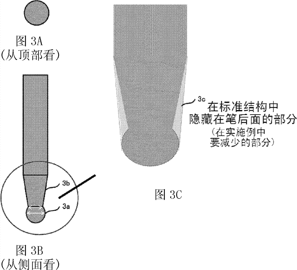
[0039] will refer to Figures 3A to 3C A stylus pen (pen) 100 according to a first example of the embodiment is described. Figures 3A to 3C The tip of the stylus pen according to the first example of the embodiment is shown in cross section. Figure 3A It is a circular cross-sectional shape seen from the base end (top) when the pen is vertically erected and is rotationally symmetrical. Figure 3B A cross-sectional shape seen from the side when the pen is vertically erected and which is a line-symmetric shape is shown. Figure 3C By Figure 3B Magnified illustrative view of the area enclosed by the circle in .
[0040] Such as Figure 3B As shown, the lead is formed such that the spherical tip portion 3a and the conical shaft portion 3b are connected to each other at a place shorter than the diameter of the spherical shape. Speaking of which, because the narrow part is set at this place, the refill is hidden compared to the standard structure Figure 3C Part 3c of the sc...
( example 2)
[0042] will refer to Figure 4A with 4B A stylus pen according to a second example of the embodiment is described. Figure 4A with 4B The tip of the stylus pen according to the second example of the embodiment is shown in cross section. Such as Figure 4A with 4B As shown, the refill tip portion is composed of a high friction material, and the refill shaft portion is composed of a transparent material such as plastic. Logos (marks for indicating touch points) are inscribed in the core shaft portion. Although the two logo shapes 4a and 4b are shown in Figure 4A with 4B , but any other shape can be used. The place where writing is done on the display can be easily identified by the marking, so that small characters can be easily written. For example, a logo can function as a touch point explicit structure.
( example 3)
[0044] will refer to Figure 5A with 5B A stylus pen according to a third example of the embodiment is described. Figure 5A with 5B The tip of the stylus pen according to the third example of the embodiment is shown in cross section. Such as Figure 5A with 5B As shown, the refill tip portion is composed of a high friction material, and the refill shaft portion is composed of a transparent material such as plastic. and Figure 4A with 4B In contrast, the refill tip portion has a protruding portion (a part of the refill tip portion that enters inside the refill shaft portion) so that the refill tip portion is hardly separated from the refill shaft portion, thereby enhancing durability in use. Logos 5a and 5b are engraved in the shaft part of the refill, similar to Figure 4A with 4B . Any other shape can be used as the logo shape. The place where writing is done on the display can be easily identified by the marking, so that small characters can be easily written. ...
PUM
 Abstract
Description
Claims
Application Information
 - R&D Engineer
- R&D Manager
- IP Professional
- Industry Leading Data Capabilities
- Powerful AI technology
- Patent DNA Extraction
Browse by: Latest US Patents, China's latest patents, Technical Efficacy Thesaurus, Application Domain, Technology Topic.
© 2024 PatSnap. All rights reserved.Legal|Privacy policy|Modern Slavery Act Transparency Statement|Sitemap