Centrifugal type non-contact wetting device of offset machine

An offset printing and centrifugal technology, applied in printing presses, rotary printing presses, offset rotary printing presses, etc., can solve the problems of contamination of fountain solution, changes in adjustment amount, and impact on printing quality, and achieves improved printing quality and precise control. effect of size

Inactive Publication Date: 2014-05-14
ZHONGSHAN FLASHLIGHT POLYTECHNIC
View PDF8 Cites 2 Cited by
  • Summary
  • Abstract
  • Description
  • Claims
  • Application Information

AI Technical Summary

Problems solved by technology

[0004] The lack of contact wetting is obvious. In the mutual contact of each water roller, the water is transferred from the water bucket to the surface of the printing plate. At the same time, the residual ink on the printing plate is also in the process of contacting each other. Reverse transfer to the bucket, contaminating the dampening solution in the bucket, degrading the performance of the dampening solution, and thus affecting the printing quality
[0005] Non-contact wetting has changed this deficiency, because a certain intermediate link in the transfer process is that the water roller does not contact, which cuts off the reverse transfer of the ink, thereby ensuring the purity of the fountain solution in the water bucket, but the existing non-contact wetting The contact wetting device is mainly a brush roller type and a water spray type (as the publication number is CN1611351A, and the patent document named as a wetting water supply device discloses a water spray type), these two wetting methods still have certain deficiencies, For example, it is difficult to accurately control the water delivery volume, and the adjustment volume changes too narrowly, etc.

Method used


Image

  • Centrifugal type non-contact wetting device of offset machine
  • Centrifugal type non-contact wetting device of offset machine
  • Centrifugal type non-contact wetting device of offset machine

Examples


Embodiment Construction

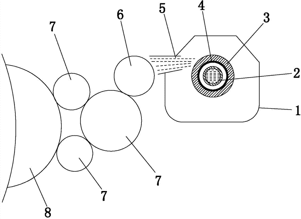
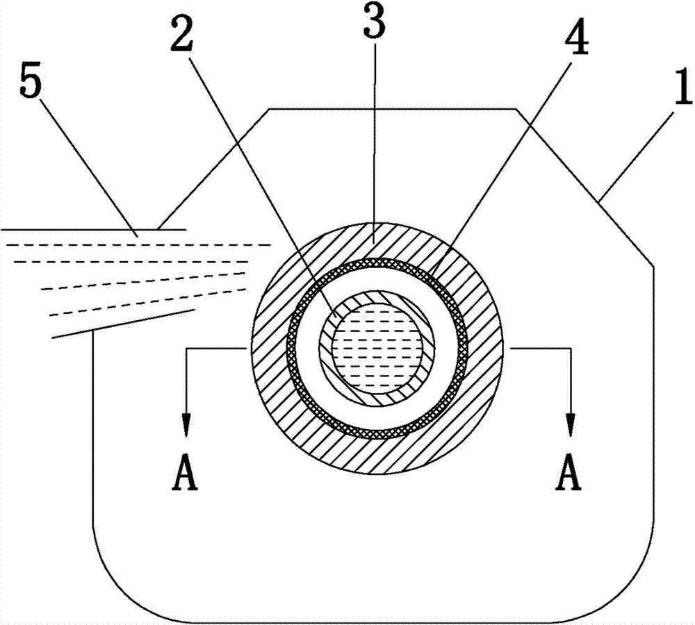
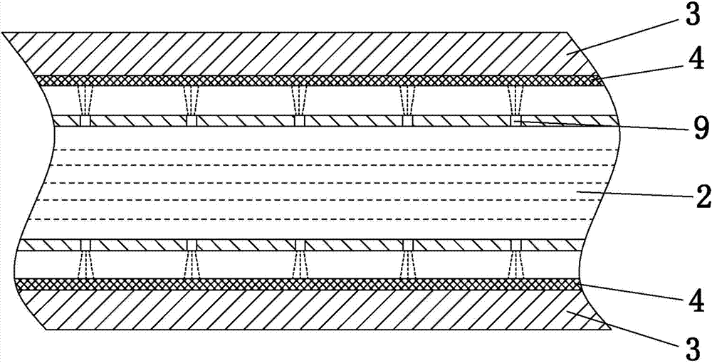
[0017] refer to Figure 1 to Figure 3 , a centrifugal non-contact wetting device for an offset printing press, used to supply water to the main water roller 6 of the offset printing press, the main water roller 6 transfers the water from the water roller group 7 to the printing plate on the printing plate cylinder 8. , the wetting device includes a water bucket 1, the water bucket is close to a closed shape, and only a water spray port 5 is provided at the position of the water bucket 1 facing the main water roller 6, and a mesh cylinder is installed in the water bucket 1 3, this net cylinder 3 is suitable for the belonging cylinder of the perforated net such as stainless steel, the inner wall of the net cylinder 3 is provided with a water-absorbing material layer 4, and the water-absorbing material layer 4 is a water-absorbing water fleece attached to the inner wall of the net cylinder 3. set. The water bucket 1 is provided with a water spray device. The water spray device i...


PUM


Abstract

The invention discloses a centrifugal type non-contact wetting device of an offset machine. The centrifugal type non-contact wetting device is used for supplying water to a main water roller of the offset machine. The main water roller transmits water to a printing plate on a printing plate barrel through a water roller set. The wetting device comprises a water hopper, and the water hopper is provided with a water spraying port facing the main water roller. A mesh barrel is installed in the water hopper, the inner wall of the mesh barrel is provided with a water absorption material layer, the water hopper is internally provided with a water spraying device, the mesh barrel is connected with a power device driving the mesh barrel to rotate, the mesh barrel is driven by the power device to rotate at a high speed to throw water away via centrifugal force so that the water can be supplied to the main water roller, the main water roller transmits the water to the printing plate on the printing plate barrel through the water roller set, the advantages of non-contact wetting are reflected, printing ink cannot flow reversely, the stepless speed change for the water supplying quantity can be achieved by controlling the revolving speed of the mesh barrel, the water quantity can be accurately controlled, and printing quality is improved.

Description

technical field [0001] The invention relates to a printing machine, in particular to a dampening device of an offset printing machine. Background technique [0002] The principle of lithographic printing (also known as offset printing) is that oil and water are immiscible. When printing, water the printing plate first, and the water is facing the entire surface of the printing plate. Because of the mechanism of the printing plate, when the printing plate is flooded with water, only the blank part of the printing plate can absorb water, while the printing plate Even if the graphic part on the printing plate encounters moisture, the moisture cannot adhere to the graphic part, and then ink the printing plate, and the ink is also facing the entire surface of the printing plate, because the blank part of the printing plate surface has already attached moisture, oil and water Incompatible, the blank part at this time can no longer adhere to ink, and the graphic part can absorb in...

Claims


Application Information

Patent Timeline
Patent Type & Authority Applications(China)
IPC IPC(8): B41F7/24
Inventor 郑新刘晓飞吴成英皮阳雪李彭黄信坤付文亭
Owner ZHONGSHAN FLASHLIGHT POLYTECHNIC
Why Eureka
Try Eureka