Water sotrage bend for water drainage

A technology of traps and drains, applied in water supply devices, indoor sanitary plumbing installations, buildings, etc., can solve problems such as drainage backflow, sensory unsanitary, backflow from the opening of the joint parts to the bath base, etc., to achieve improved The effect of drainage flow

Active Publication Date: 2008-12-24
MARUICHI VALVE CO LTD
View PDF3 Cites 0 Cited by
  • Summary
  • Abstract
  • Description
  • Claims
  • Application Information

AI Technical Summary

Problems solved by technology

[0037] In the case of a common drain trap for washing machines, an anti-foam pipe is provided to prevent the foam from flowing back into the room during the drainage. The foam in the water is effectively suppressed, but because of the narrow opening area of ​​the outlet, it also leads to a very unsatisfactory result of the drainage flow
[0038] In addition, in the case of a normal bath drain trap, when the amount of water flowing into the trap body is large, etc., the drainage in the trap body may flow to the drain side of the trap body due to insufficient flow. Reverse flow, or reverse flow of water to the base of the wash basin
In addition, in addition to backflow to the base side of the washing field, sometimes it will flow back to the opening of the elbow joint part through the branch pipe of the trap body. Backflow from the opening to the base of the bath, or backflow of drainage to the upper part of the bath
[0039] Especially when there is a phenomenon of backflow of drainage on the base of the washing place and in the bathtub, since this phenomenon is intuitive and visible to the user, it feels extremely unhygienic on the senses
Since the base of the bath is usually imperviously connected with backing plates and other objects, it is impossible to visually confirm from the side of the base of the washing field to the base of the bath. Sweeping and cleaning, due to the obstruction of the backing plate, it is often difficult to clean, and in the worst case, it will cause problems such as bad smell

Method used


Image

  • Water sotrage bend for water drainage
  • Water sotrage bend for water drainage
  • Water sotrage bend for water drainage

Examples


Embodiment 1

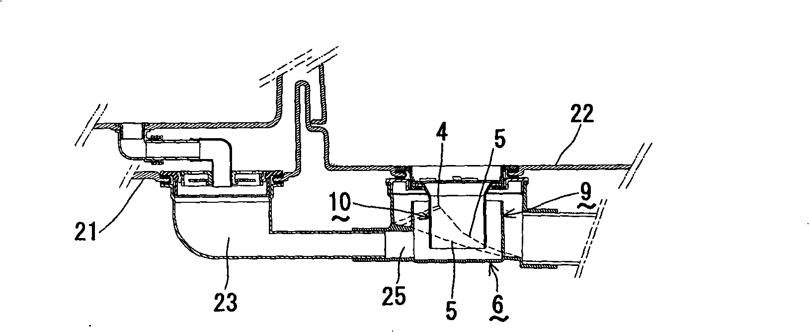
[0121] The drainage trap of the present invention is figure 1 , Figure 8-10 drain trap as shown in the illustration. Below, for figure 1 , Figure 8-Figure 10 The embodiment of the drain trap shown in the figure will be described with reference to the drawings.

[0122] figure 1 , Figure 8-Figure 10 The drainage trap of this embodiment shown in the figure is installed in the bathroom described below.

[0123] The bathroom is composed of a bathtub, a bathtub base 21 and a washing place base 22 , wherein the bathtub base 21 is used to place the bathtub, and the washing place base 22 forms a washing place adjacent to the bathtub base 21 . In addition, openings are formed on the bathtub base 21 and the washing place base 22, and a drainage trap is connected and arranged on the inner surface side of the openings.

[0124] The drainage trap is composed of the trap body 6, the flange, the water sealing bowl 9, the water sealing cylinder 10, the sieve plate part 24, and th...

Embodiment 2

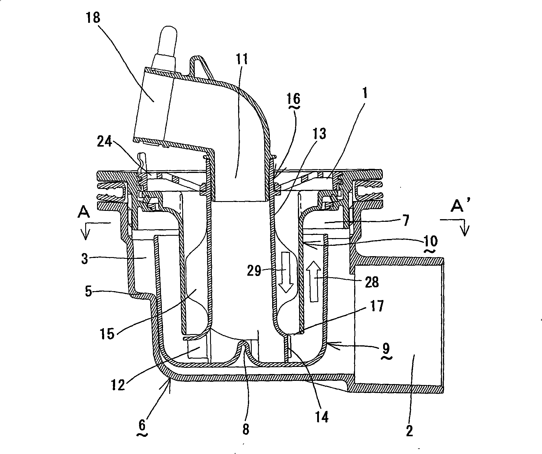
[0143] The drainage trap of the present invention is Figure 2-Figure 11 drain trap as shown in the illustration. Below, for Figure 2-Figure 11 The embodiment of the drain trap shown in the figure will be described with reference to the drawings.

[0144] Figure 2-Figure 11 The drainage trap shown in the figure is installed on the waterproof base 20 for the washing machine described below.

[0145] The top of the waterproof base 20 for the washing machine is just the washing machine body, and the bottom surface of the waterproof base has an opening.

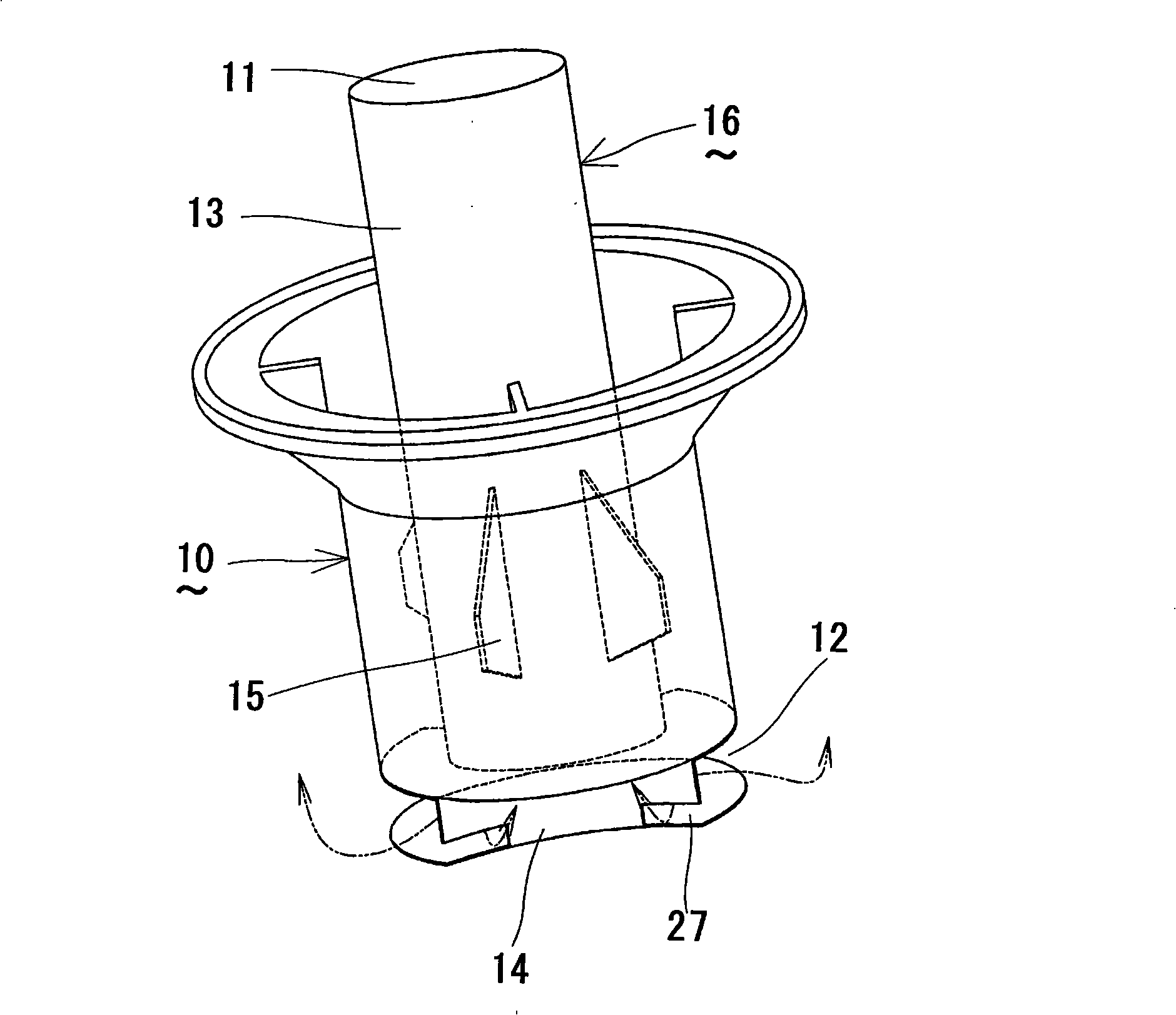
[0146] The drainage trap is composed of the trap body 6, the flange, the water sealing bowl 9, the water sealing cylinder 10, the anti-bubble pipe 16, the joint 18, and the sieve plate part 24 as described below.

[0147] The water trap body 6 is in the shape of a container, and includes: a discharge port 1 through which the upper part of the drain flows in, and a discharge port 2 through which the drain is discharged from ...

Embodiment 3

[0170] Figure 2-Figure 11 The drain trap shown in is installed on the waterproof base 20 for the washing machine described below.

[0171] The top of the waterproof base 20 for the washing machine is just the washing machine body, and the bottom surface of the waterproof base has an opening.

[0172] The drainage trap is composed of the trap body 6, the flange, the water sealing bowl 9, the water sealing cylinder 10, the anti-bubble pipe 16, the joint 18, and the sieve plate part 24 as described below.

[0173] The water trap body 6 is in the shape of a container, and includes: a discharge port 1 through which the upper part of the drain flows in, and a discharge port 2 through which the drain is discharged from the side. In addition, at the discharge port 1, a female thread screwed with the flange described later is processed, and the pipe body is connected to the discharge port 2, and finally connected to the downpipe. In addition, a water sealing bowl 9 to be described l...


PUM


Abstract

The invention discloses a water draining siphon trap, comprising a siphon trap body, a water sealing bowl and a water sealing cylinder, wherein, six bottom surfaces of the siphon trap body 6 protrude to form vertex parts, and a bevel surface downgoing continuously is arranged from the vertex parts to the lowest end of an outlet opening toward the two sides. In addition, an anti-foam pipe is arranged also and a guide part of the anti-foam pipe is provided with a through hole or a cut groove. The water draining siphon trap ensures that the phenomenon that the foam does not flow to one side of a machine reversely does not exist in the draining environment that the washing machine or a bathtub is surrounded by a large amount of foam, makes the drainage smooth, increases the drainage flow rate, and can prevent the water draining siphon trap from breaking a seal.

Description

【Technical field】 [0001] 【0001】 [0002] The invention relates to a drainage trap for preventing foul odor from sewers and harmful insects from flowing backward to the indoor side. 【Background technique】 [0003] 【0002】 [0004] Regarding our common drainage traps, there are generally as many as Figure 12 shown in . Compare the bottom side Figure 12 The picture shown, while explaining the common drainage trap. [0005] Figure 12 The prior art drain trap shown is mounted on a waterproof base for a washing machine as described below. The upper part of the waterproof base for the washing machine is just the washing machine body, and the bottom surface of the waterproof base has an opening. [0006] The drainage trap is composed of the trap body, flange plate, water sealing bowl, water sealing cylinder, anti-foam pipe, joints, and sieve plate components described below. [0007] The body of the water trap is in the shape of a container, including: a discharge port for th...

Claims


Application Information

Patent Timeline
Patent Type & Authority Applications(China)
IPC IPC(8): E03C1/28
Inventor 堀江進狩野仁孝
Owner MARUICHI VALVE CO LTD
Why Eureka
Try Eureka