Kitchen waste biodegradation waste gas treatment and waste heat recovery integrated device

A waste heat recovery device and biodegradation technology, used in gas treatment, heat exchangers, indirect heat exchangers, etc., can solve the problems of large exhaust gas transportation wind resistance, unfavorable exhaust gas emissions, and long exhaust gas transportation travel, and achieve exhaust gas transportation wind resistance. Small, improve heat exchange efficiency, and reduce exhaust emissions

Pending Publication Date: 2021-07-13
广东亿云智能环保科技有限公司
View PDF22 Cites 0 Cited by
  • Summary
  • Abstract
  • Description
  • Claims
  • Application Information

AI Technical Summary

Problems solved by technology

[0004] 1. The waste gas produced by the biodegradation of food waste is transported to the bottom of the spray tube through the gas collecting hood. After being sprayed with water, the purified waste gas is transported from the upper part of the spray tube to the drying device. Because the spraying process will Block the exhaust gas transmission, causing the exhaust gas to flow backwards, resulting in a large wind resistance in the exhaust gas transmission, which is not conducive to the emission of exhaust gas
[0005] 2. The overall structure of the above-mentioned device is complex. The waste gas is transported through pipelines between the gas collection hood and the water circulation spray device, the water circulation spray device and the drying device, and the drying device and the cooperative catalytic reaction device. The pipeline transportation distance is long, resulting in exhaust gas discharge The transportation stroke is far, the energy consumption is high, and the purification efficiency is low
[0006] 3. In order to improve the degradation efficiency, the fermentation chamber needs to be heated to a certain temperature during the decomposition process of food waste. Therefore, the exhaust gas contains waste heat, and the heat is wasted due to the lack of heat recovery.

Method used


Image

  • Kitchen waste biodegradation waste gas treatment and waste heat recovery integrated device
  • Kitchen waste biodegradation waste gas treatment and waste heat recovery integrated device
  • Kitchen waste biodegradation waste gas treatment and waste heat recovery integrated device

Examples


Embodiment Construction

[0035] In order for those skilled in the art to better understand the technical solution of the present invention, the present invention will be further described below in conjunction with the examples and accompanying drawings, but the embodiments of the present invention are not limited thereto.

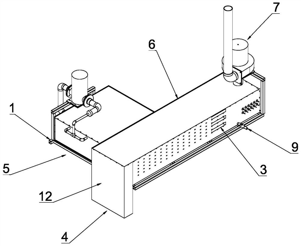
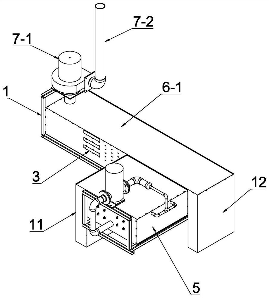
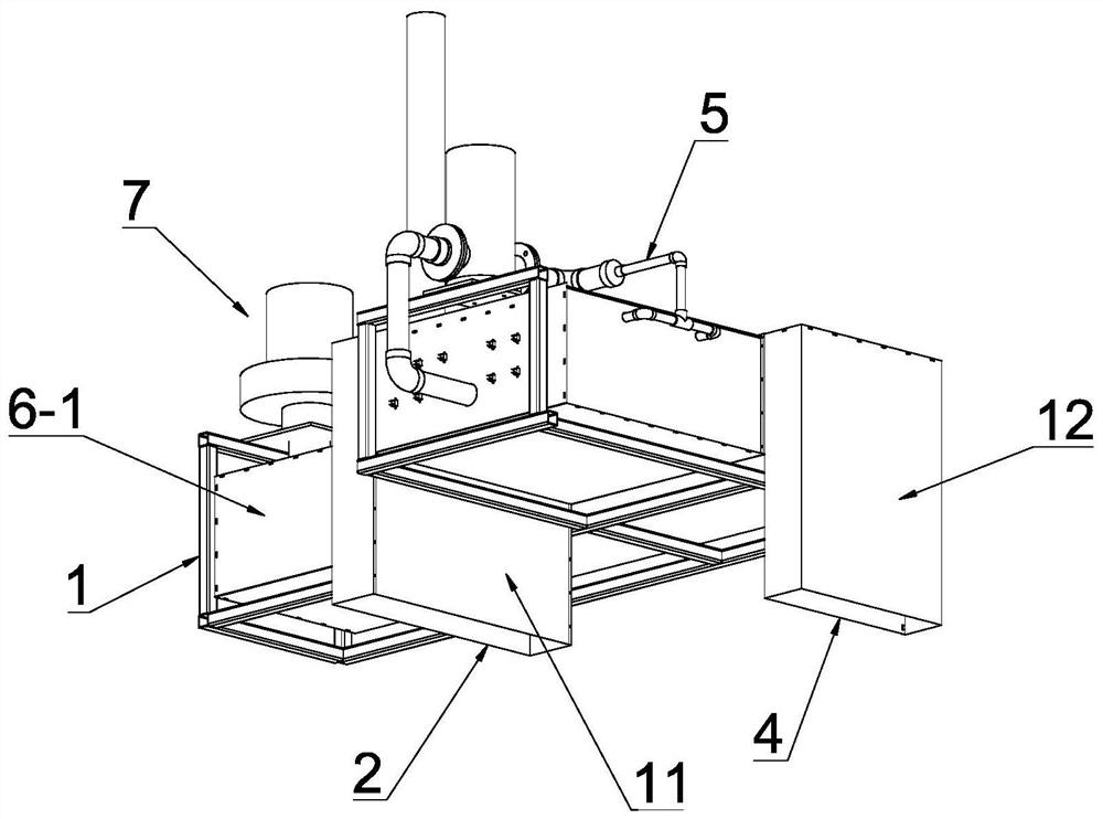
[0036] see Figure 1-Figure 3 , this embodiment discloses an integrated device for biodegradable waste gas treatment and waste heat recovery of kitchen waste, including a frame 1, a waste gas inlet 2, a fresh air inlet 3, a return air port 4, a spray purification device 5, and waste heat recovery device 6 and exhaust device 7.

[0037] see Figure 1-Figure 3 and Figure 6-Figure 8 , the spray purification device 5 includes a spray box 5-1 installed on the frame 1 and a spray mechanism arranged on the top of the spray box 5-1; wherein, the spray mechanism is a circulating spray mechanism, including a water pump 5-2 arranged on the top of the spray box 5-1, a spray pipe 5-3 for sp...


PUM


Abstract

The invention discloses a kitchen waste biodegradation waste gas treatment and waste heat recovery integrated device, which comprises a waste gas inlet, a fresh air inlet, an air return port, a spraying purification device, a waste heat recovery device and an exhaust device, and is characterized in that the spraying purification device comprises a spraying box and a spraying mechanism; the waste heat recovery device comprises at least one waste gas conveying channel and at least one fresh air conveying channel, wherein the waste gas conveying channel and the fresh air conveying channel are connected with each other to form a stacked structure; the waste gas inlet is communicated with the side surface of the spraying box; one end of the waste gas conveying channel is communicated with the other side face of the spraying box, and the other end of the waste gas conveying channel is communicated with the exhaust device; and one end of the fresh air conveying channel communicates with the fresh air inlet, and the other end of the fresh air conveying channel communicates with the air return port. The device is simple in structure, small in wind resistance in the waste gas purification process and short in waste gas emission stroke, heat of waste gas can be recycled, and energy waste is reduced.

Description

technical field [0001] The invention relates to food waste treatment equipment, in particular to an integrated device for food waste biodegradation waste gas treatment and waste heat recovery. Background technique [0002] Organic waste, also known as wet waste, refers to waste containing organic components in domestic waste. In daily life, the main organic waste is kitchen waste, which is the organic waste formed by residents in the process of daily consumption, mainly referring to fruit peels, vegetable peels, leftovers, vegetable peels, etc. If it is directly discharged into nature without treatment, it will easily rot and deteriorate, emit foul smell, and spread bacteria and viruses. In our country, most of the garbage is treated by landfill, but it is difficult to treat the landfilled garbage harmlessly, and there are great hidden dangers, which will cause serious pollution of groundwater and occupy a large amount of land resources; while garbage incineration treatment...

Claims


Application Information

Patent Timeline
Patent Type & Authority Applications(China)
IPC IPC(8): B01D53/18B01D53/00F28D21/00
CPCB01D53/18B01D53/007F28D21/0014B01D2257/91B01D2259/804
Inventor 段先云钟更铜张丽云
Owner 广东亿云智能环保科技有限公司
Why Eureka
Try Eureka