A flyback synchronous rectifier circuit

A synchronous rectification and circuit technology, applied in the direction of electrical components, adjusting electrical variables, high-efficiency power electronic conversion, etc., can solve the problems of large body diode conduction loss, large delay, small circulating current, etc., to suppress voltage spikes and power consumption small, efficiency-enhancing effect

Active Publication Date: 2022-07-29
西安电子科技大学芜湖研究院 +1
View PDF7 Cites 0 Cited by
  • Summary
  • Abstract
  • Description
  • Claims
  • Application Information

AI Technical Summary

Problems solved by technology

The turn-on time of the circuit voltage is obtained by comparing the sampling circuit with the reference value, and the delay is relatively large, resulting in the body diode conduction loss of the synchronous rectification MOSFET (Metal-Oxide-Semiconductor Field-Effect Transistor, Metal-Oxide-Semiconductor Field-Effect Transistor) when turned on Larger, the detection of input current and output level is used when turning off, the time is longer, the turn-off time will be later than the actual zero current moment, and a small circulating current will be generated

Method used


Image

  • A flyback synchronous rectifier circuit
  • A flyback synchronous rectifier circuit
  • A flyback synchronous rectifier circuit

Examples


Embodiment 1

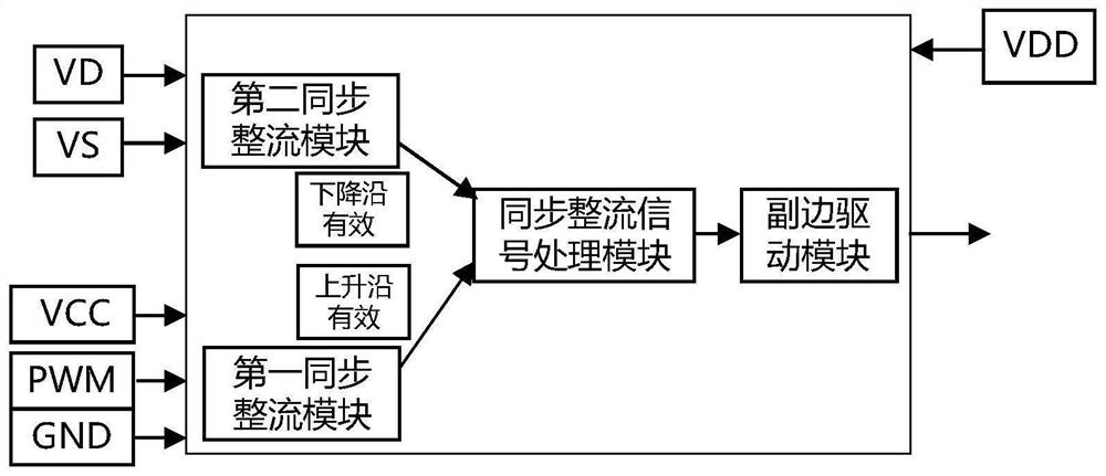
[0033] See figure 1 , figure 1 It is a schematic structural diagram of a flyback synchronous rectifier circuit provided by an embodiment of the present invention. This embodiment provides a flyback synchronous rectification circuit, the flyback synchronous rectification circuit includes a first synchronous rectification module, a second synchronous rectification module, a synchronous rectification signal processing module and a secondary side drive module, the first synchronous rectification module and the second synchronous rectification module The synchronous rectification module is connected to the synchronous rectification signal processing module, and the synchronous rectification signal processing module is connected to the secondary side drive module, wherein the first synchronous rectification module is used to generate the secondary side drive control signal complementary to the control signal of the primary side MOSFET; the second synchronous rectification module Th...


PUM


Abstract

The invention discloses a flyback synchronous rectification circuit, comprising: a first synchronous rectification module for generating a secondary side drive control signal complementary to a control signal of a primary side MOSFET; a second synchronous rectification module for The synchronous rectification control signal is generated by the drain level and the source level of the synchronous rectification signal; the synchronous rectification signal processing module is used to collect the secondary side drive control signal and the synchronous rectification control signal, and according to the rising edge of the secondary side drive control signal and all The falling edge of the driving control signal obtains the driving signal of the secondary side MOSFET; the secondary side driving module is used for driving the secondary side MOSFET by using the driving signal. The entire flyback synchronous rectifier circuit can improve the efficiency of the flyback circuit at the beginning of turn-on and turn-off, which can improve the efficiency at light load and heavy load; at the same time, it can suppress the voltage spike on the secondary side, Improve circuit reliability.

Description

technical field [0001] The invention belongs to the technical field of power electronics, and in particular relates to a flyback synchronous rectifier circuit. Background technique [0002] Synchronous rectifier circuits are widely used and can significantly improve the conversion efficiency of power modules. When the synchronous rectifier circuit is under light load or no load, the inductor current is discontinuous. At this time, the synchronous rectification signal that is completely opposite to the input will cause a reverse current in the output, which will generate excess circulating current in the circuit and increase the light load and no load. In parallel, voltage spikes may also be generated on the secondary side, causing damage to the synchronous rectifier tube; and the synchronous rectification technology that detects the relationship between the output and the transformer level, due to sampling and signal delay, will cause synchronous rectification to appear befo...

Claims


Application Information

Patent Timeline
Patent Type & Authority Patents(China)
IPC IPC(8): H02M3/335
CPCH02M3/33592Y02B70/10
Inventor 张艺蒙孙世凯郭辉张玉明吴勇
Owner 西安电子科技大学芜湖研究院
Why Eureka
Try Eureka