Forced lubrication device

A technology of lubricating device and lubricating box, applied in the field of metal drawing processing, can solve the problems of scratches, inability to form, lack, etc., and achieve the effect of reducing loss, ensuring quality, and easy adsorption

Inactive Publication Date: 2016-06-15
SHANGHAI YIHAO ENVIRONMENTAL PROTECTION EQUIPCO
View PDF6 Cites 0 Cited by
  • Summary
  • Abstract
  • Description
  • Claims
  • Application Information

AI Technical Summary

Problems solved by technology

However, since the surface of the steel brush after derusting is relatively bright, it is not easy to attach wire drawing powder, and there is no effective pressurized chamber in the lubrication box body, and the lubricant in the lubrication box body is easily squeezed out and reflowed in the reverse direction, and it is impossible to form a thicker Lubricating film, so it will often cause steel brush to scratch and damage the wire drawing die, affecting normal production

Method used


Image

  • Forced lubrication device

Examples


Embodiment Construction

[0015] In order to deepen the understanding of the present invention, the present invention will be further described below in conjunction with the embodiments and accompanying drawings. The embodiments are only used to explain the present invention and do not constitute a limitation to the protection scope of the present invention.

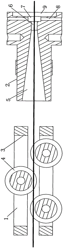
[0016] The forced lubricating device as shown in the accompanying drawings includes a lubricating box body 1 and a forced pipe 2 connected in the middle. The lubricating box body 1 is arranged at the front end of the forced pipe 2. The lubricating box body 1 includes a powder clamp 3 and three equal-diameter Rollers 4, the wire rod can pass between the rollers 4. The forced pipe 2 includes a conical inlet 5 , a working section 6 , a high-pressure section 7 , a vent hole 8 and a joint position 9 . The diameter of the working section 6 is 0.6-0.8mm larger than the diameter of the wire. The conical inlet 5 is set at the front end of the working sect...


PUM

PropertyMeasurementUnit
diameteraaaaaaaaaa

Abstract

The invention discloses a forced lubricating device, which comprises a lubricating box body and a forced pipe connected in the middle, wherein the lubricating box body is arranged at the front end of the forced pipe, and the forced pipe includes a tapered inlet, a working section, a high pressure section, Ventilation hole and joint position, the tapered inlet is set at the front end of the working section, the high-pressure section is set at the rear end of the working section, the vent hole is connected with the high-pressure section, and the joint position is set at the high-pressure section rear end. The forced lubricating device of the present invention uses the high temperature generated by the wire drawing die during the wire drawing process to transmit it to the forced tube, combined with the narrow space of the forced tube, the wire drawing powder is melted into a semi-solid state, so that the surface of the steel wire is 100% attached For wire drawing powder, the tube body of the forced tube adopts the shape of a bell mouth, which is convenient for more wire drawing powder to be transported into the wire drawing die, and the high-pressure section is added to make the wire drawing powder more easily adsorbed on the surface of the wire without reverse flow, ensuring The quality of drawing products.

Description

technical field [0001] The invention relates to a device in the field of metal drawing, in particular to a forced lubrication device for metal drawing. Background technique [0002] Metal drawing is a method of forcibly pulling a larger section of metal material through a die hole to obtain the required section shape and size. During the current metal drawing process, the steel wire enters from the entrance of the lubricating box, passes through the lubricating box and enters the mold box, and the motor at the entrance of the lubricating box drives or rotates and stirs. The speed and start-stop time can be adjusted at any time by the motor. . In the drawing production, a small part of the lubricant will make the steel wire advance at a certain speed, and be adsorbed on the surface of the steel wire by the carrier (borax pre-coated on the surface of the steel wire) to form a lubricating film, paving the way for subsequent drawing. However, since the surface of the steel bru...

Claims


Application Information

Patent Timeline
Patent Type & Authority Patents(China)
IPC IPC(8): B21C9/00
Inventor 赵伟民张仁标樊春三
Owner SHANGHAI YIHAO ENVIRONMENTAL PROTECTION EQUIPCO
Why Eureka
Try Eureka