Method, device and communication system for determining proximity relation between user devices

A proximity relationship, user equipment technology, applied in wireless communication, electrical components, network data management and other directions, can solve the problem of no user equipment proximity relationship discovery and so on

Active Publication Date: 2014-06-11
DATANG MOBILE COMM EQUIP CO LTD
View PDF6 Cites 31 Cited by
  • Summary
  • Abstract
  • Description
  • Claims
  • Application Information

AI Technical Summary

Problems solved by technology

[0007] Embodiments of the present invention provide a method, device and communication system for determining the proximity relationship between user equipments, which are used to s

Method used


Image

  • Method, device and communication system for determining proximity relation between user devices
  • Method, device and communication system for determining proximity relation between user devices
  • Method, device and communication system for determining proximity relation between user devices

Examples


Embodiment 1

[0161] Embodiment 1. In this embodiment, UE_A is attached to MME_A, and the application service it currently uses is APP_ID. This application service triggers UE_A to request from the network side (ie MME_A) whether its friend UE_B (whose application ID is APP_ID_B) has a neighbor relationship ; see Figure 6 As shown, the method of the present embodiment includes the following steps:

[0162] Step 61, UE_A sends an Uplink generic NAS transport message (Genericmessage container (APP_ID_B, APP_ID), ProSe_discovery_request) to MME_A, requesting MME_A to determine whether UE_B is in a neighboring relationship with it (that is, to determine whether UE_A and UE_B meet the neighboring relationship discovery criteria); among them, APP_ID is the application ID of the application service currently used by UE_A, and APP_ID_B is the application ID of UE_A's friend;

[0163] Step 62, MME_A determines that UE_A has a subscription that allows discovery of other terminals, and the 3GPP netw...

Embodiment 2

[0171]Embodiment 2. In this embodiment, UE_A is attached to MME_A, and its current application service is APP_ID. This application service triggers UE_A to ask the network side (ie MME_A) whether its friend UE_B (MSISDN is MSISND_B) has a neighbor relationship; the application The server binds the user's application identity and 3GPP network identity, and UE_B authorizes the application server to provide its own 3GPP network identity to its friends; and the MME in the 3GPP network supports searching the MMcontext of the corresponding UE through MSISDN; see Figure 7 As shown, the method of the present embodiment includes the following steps:

[0172] Step 71, UE_A sends an Uplink generic NAS transport message (Genericmessage container (MSISDN_B, APP_ID), ProSe_discovery_request) to MME_A, requesting MME_A whether UE_B is in a neighboring relationship with it (that is, judging whether UE_A and UE_B meet the neighboring relationship discovery criteria); among them, APP_ID is The...


PUM


Abstract

The invention discloses a method, device and communication system for determining the proximity relation between user devices. The method, device and communication system are used for solving the problem that a solution to discovery of the proximity relation between the adjacent user devices is not available currently. The method comprises the steps that after a first MME receives a proximity relation discovery request sent by a first terminal, according to the subscription information, stored by the first MME, of the first terminal, it is determined that the first terminal has the authority to allow discovery of subscriptions of other terminals and the application service currently used by the first terminal has the authority to allow use of adjacent communication services; after it is determined that a second terminal has the subscriptions which are allowed to be discovered by other terminals, according to the position information of the first terminal and the second terminal, whether the first terminal and the second terminal meet proximity relation judgment criteria or not is judged, and a judgment result is sent to the first terminal. By means of the method, device and communication system, a solution to determination of the proximity relation between the user devices is provided, and the discovery process of the proximity relation between the user devices is completed.

Description

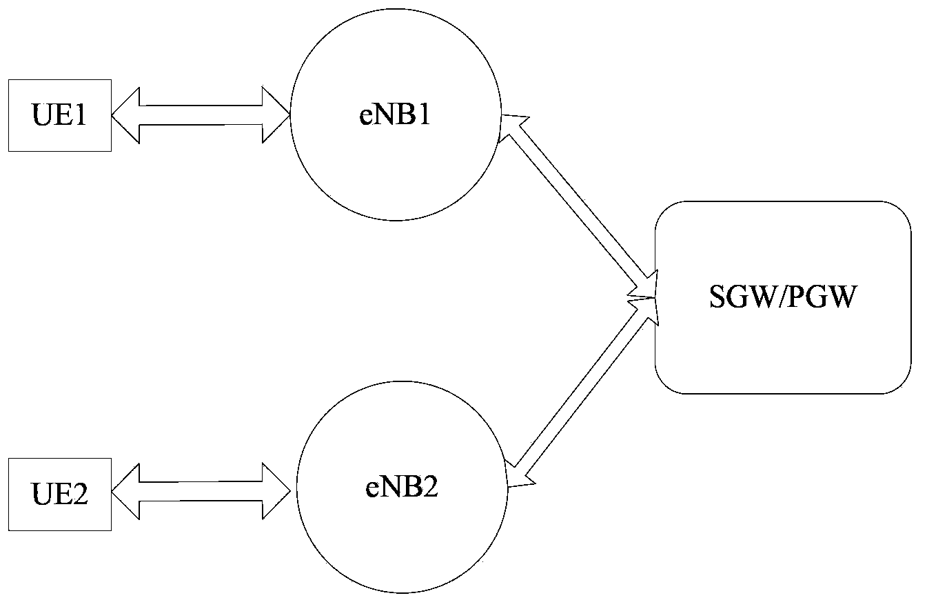
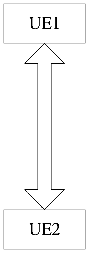
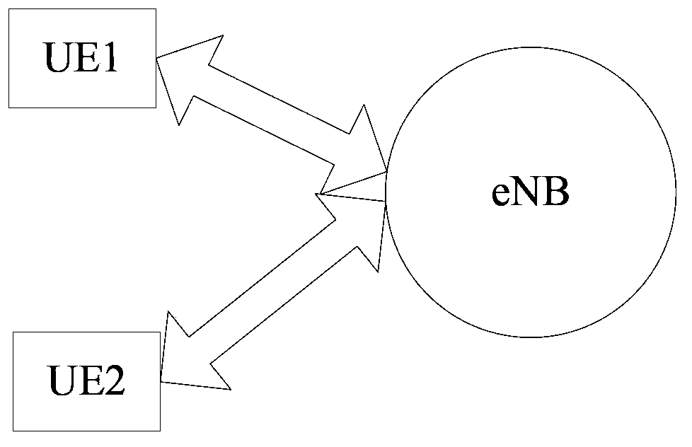
technical field [0001] The present invention relates to the technical field of wireless communication, in particular to a method, device and communication system for determining the proximity relationship between user equipments. Background technique [0002] For the communication process between two user equipment (User Equipment, UE) defined in the current 3rd Generation Partnership Project (3rd Generation Partnership Project, 3GPP), see figure 1 As shown, the process of UE1 sending data to UE2 includes: [0003] UE1 sends data to eNB1 serving it; eNB1 passes the data to Serving Gateway (Serving Gateway, SGW) / Packet Data Network Gateway (PDN GW) after receiving the data; SGW / PGW receives the data After receiving the data, route the data to the SGW / PGW serving UE2 according to the routing identifier of UE1; since the SGW / PGW of UE1 and UE2 in the figure are the same, the SGW / PGW serving UE2 transfers the data to the SGW / PGW serving UE2 Finally, eNB2 transmits the data to ...

Claims


Application Information

Patent Timeline
IPC IPC(8): H04W8/00H04W36/00
Inventor 康艳超
Owner DATANG MOBILE COMM EQUIP CO LTD
Why Eureka
Try Eureka