
A digital filter design method

A digital filter and design method technology, applied in the field of communication, can solve problems such as difficult to achieve asymmetrical frequency response, multi-band frequency response, etc., and achieve the effects of easy application, flexible frequency response, and frequency response control

Inactive Publication Date: 2016-06-22
唐萍
View PDF3 Cites 0 Cited by
  • Summary
  • Abstract
  • Description
  • Claims
  • Application Information

AI Technical Summary

Problems solved by technology

[0006] The purpose of the present invention is to overcome the deficiencies and defects existing in the prior art, solve the problems existing in the existing IIR digital filter design method, that is, it is difficult to realize the shortcomings such as asymmetric frequency response and multi-band frequency response, and propose a A Digital Filter Design Method

Method used


Image

  • A digital filter design method
  • A digital filter design method
  • A digital filter design method

Examples


Embodiment Construction

[0021] The present invention will be further described below in conjunction with the drawings and embodiments.

[0022] Assuming that the digital corner frequency is represented by ω, the digital filter to be designed has M frequency bands (M is a natural number greater than or equal to 1; when M is equal to 1, it is a single frequency band; when M is greater than 1, it is a multiple frequency band), These M frequency bands are located in [ω d,k ,ω u,k ], where k=1,...,M,ω u,i And ω d,i Are the upper and lower boundary corner frequencies of the k-th frequency band; the digital filter to be designed has N transmission zero points, where N p Transmission zeros are at zero frequency, N m Transmission zeros are located at a limited frequency, N L The transmission zeros are located at frequency π, the total number of which is N=N p +N m +NL, these transmission zeros can be pure imaginary numbers, pure real numbers or even complex numbers, use p 0k (Where k=1,...,N).

[0023] The imple...


PUM


Abstract

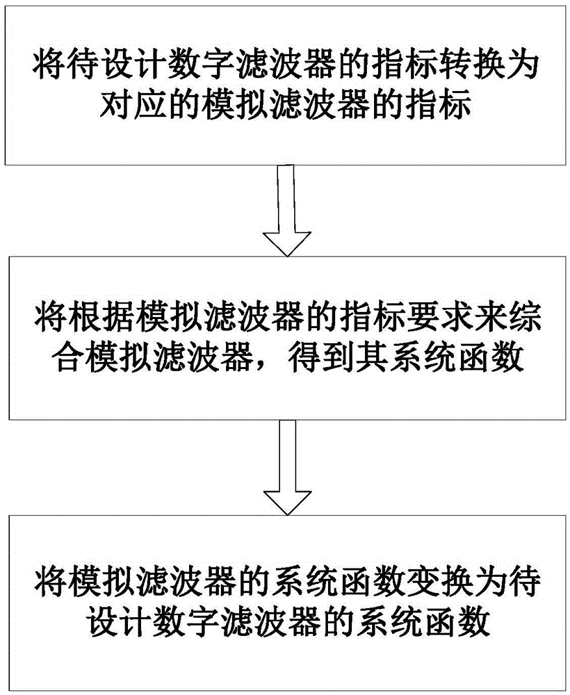
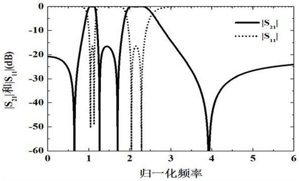
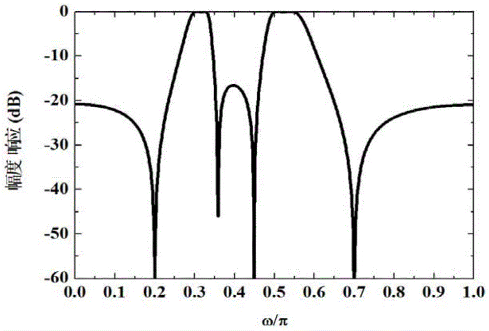
The invention discloses a method for designing a digital filter. The method specifically comprises the steps that the index of the digital filter to be designed is converted into the index of a corresponding analog filter; the analog filter is integrated directly in a corresponding frequency domain according to the index of the corresponding analog filter, so that a system function of the analog filter is obtained; the obtained system function of the analog filter is converted into the system function of the digital filter to be designed. By the aid of the method for designing the digital filter, asymmetrical frequency response of single-frequency bands or multi-frequency bands can be achieved, the order of the filter cannot be changed, the frequency response of the filter can be adjusted flexibly by changing the position of a transmission zero, and thus the filter can meet actual requirements. The bend width of each frequency band can be accurately controlled, and fluctuation in each band is constant.

Description

Technical field [0001] The invention belongs to the field of communication technology, and relates to a digital filter design method, in particular to a digital infinite impulse response filter design method with generalized Chebyshev characteristics. Background technique [0002] Digital signal processing has been widely used in many fields such as communication, voice, image, automatic control, radar, military, aerospace, medical and household appliances. A digital filter is a discrete-time system that filters digital signals to obtain desired response characteristics. It is mainly used to transform, enhance, filter, estimate, and identify signals, and is an important part of the process of information acquisition, processing and utilization. From the structural point of view, digital filters can be divided into finite impulse response (FIR) digital filters and infinite impulse response (IIR) digital filters. Since the pole of the system function of the FIR filter is fixed at...

Claims


Application Information

Patent Timeline
Patent Type & Authority Patents(China)
IPC IPC(8): H03H17/00
Inventor 唐萍肖飞
Owner 唐萍
Learn More