Dehumidifying device of heat pump

A heat pump dehumidification and regenerator technology, applied in the field of heat pumps, can solve the problems of increasing the wind speed of the drying system, complicated installation, and large compression ratio of the compressor, so as to achieve the effects of increasing the air volume of the condenser, improving the dehumidification performance, and saving operating costs

Active Publication Date: 2014-09-10
石曾矿
View PDF7 Cites 15 Cited by
  • Summary
  • Abstract
  • Description
  • Claims
  • Application Information

AI Technical Summary

Problems solved by technology

The air volume of the evaporator and condenser adopts the same dehumidification air volume, and the air heat exchange process of the condenser is a process of sensible heat temperature rise, resulting in high condensation pressure, large compression ratio of the compressor, and insufficient deh

Method used


Image

  • Dehumidifying device of heat pump
  • Dehumidifying device of heat pump
  • Dehumidifying device of heat pump

Examples


Embodiment 1

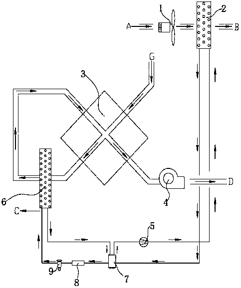
[0029] Heat pump dehumidifiers such as figure 1 As shown, it includes a refrigeration cycle, a dehumidification module and a circulating air module. The refrigeration cycle includes a first condenser 2, an evaporator 6, an expansion valve 9 and a compressor 5. The outlet of the compressor 5 is connected to the The inlet of the first condenser 2 is connected, the outlet of the first condenser 2 is connected with the inlet of the expansion valve 9 through a filter 8 through a copper pipe, and the outlet of the expansion valve 9 is connected with the inlet of the evaporator 6, so The outlet of the evaporator 6 is connected to the compressor 5 through a copper pipe to form a refrigeration cycle; the dehumidification module includes a regenerator 3 and a dehumidification fan 4, the hot side of the regenerator 3 is provided with an air inlet G, and the regenerator The hot side air outlet of heater 3 is connected with the cold side inlet of regenerator 3 through pipeline through evap...

Embodiment 2

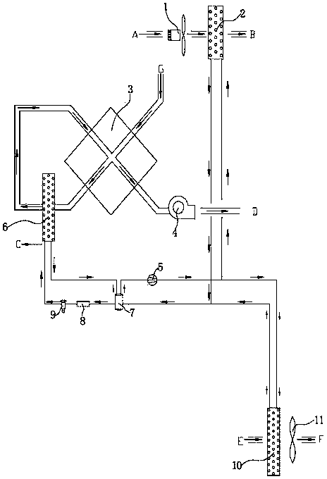
[0032] On the basis of the mechanism of Embodiment 1, the heat pump dehumidification device of the present invention also includes a second condenser 10, the outlet of the compressor 5 is connected to the inlet of the second condenser 10 through a pipeline, and the second condenser 10 The outlet of the evaporator 6 is connected to the inlet of the evaporator 6 through a filter 8 through a pipeline, the outlet of the expansion valve 9 is connected to the inlet of the evaporator 6, and the outlet of the evaporator 6 is connected to the compressor 5 through a pipeline to form an outdoor refrigeration cycle. A second circulating air module is arranged beside the second condenser 10 . The second circulating air module includes a second circulating fan 11 , and the second circulating fan 11 is installed beside the second condenser 10 . The air is output from the air outlet F of the second circulating fan 11 through the second condenser 10 through the inlet E, the air is cooled by th...

Embodiment 3

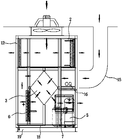
[0034] Such as Figure 7 with Figure 8As shown, wherein, the first condenser 2 or the second condenser 10 and the circulation fan or the second circulation fan 11 are installed in one body to form an independent module. The first condenser 2 or the second condenser 10 are respectively connected to the compressor 5 and the filter 8 through copper pipes 15; in this way, the installation is more flexible, can no longer be controlled by space, and the structure is more compact, and the heat exchange The efficiency is effectively improved, while reducing unit installation costs and saving installation space.

[0035] Wherein, the bracket 12 is made of profiled steel, sheet metal processing or aluminum alloy, which has a strong structure and saves cost. The outer shell adopts a composite insulation board with thermal insulation performance, which is not less than 25mm, and the inner layer of the composite board is a hot-dip galvanized steel plate, aluminum plate or stainless stee...


PUM


Abstract

The invention discloses a dehumidifying device of a heat pump. The dehumidifying device comprises a refrigerating cycle, a dehumidifying module and a circulating air module. The refrigerating cycle comprises a first condenser, an evaporator, an expansion valve and a compressor; the dehumidifying module comprises a heat regenerator, air is fed into the heat regenerator from a hot side, a hot-side air outlet of the heat regenerator is connected with a cold-side inlet of the heat regenerator by a pipeline via the evaporator, and a cold-side outlet of the heat regenerator is connected with an air outlet pipeline; the circulating air module comprises a circulating fan, and the circulating fan is mounted beside the first condenser. The dehumidifying device has the advantages that the dehumidifying performance can be improved, the air volume of the condenser can be increased, the condensation pressures can be reduced, a comprehensive dehumidifying performance ratio of the dehumidifying heat pump can be increased by 20% at least, the operating expense can be greatly saved, the using temperature range of identical refrigerants in drying procedures can be expanded, the unit mounting expense can be reduced, and mounting spaces can be saved.

Description

【Technical field】 [0001] The invention relates to the field of heat pumps, in particular to a heat pump dehumidification device. 【Background technique】 [0002] The existing dehumidification heat pump (heat pump dehumidification dryer) generally adopts the principle of single cooling and dehumidification of the evaporator. Part of the cooling load of the evaporator is used for cooling the drying medium (air, etc.) to the dew point temperature, and part of the cooling load is used for the dehumidification process, especially in the later stage of drying. Most of the cooling load of the evaporator is only used to cool the drying medium, and the dehumidification capacity is small. The dehumidification performance ratio (SMER) of the dehumidification heat pump (heat pump dehumidification dryer) in the entire drying period is only 1~3kg water / kw.h, and the humidity is further reduced. Not even condensation. The air volume of the evaporator and condenser adopts the same dehumidif...

Claims


Application Information

Patent Timeline
IPC IPC(8): F26B21/00F25B41/06F25B47/00F25B41/31
CPCY02B30/52
Inventor 石曾矿
Owner 石曾矿
Why Eureka
Try Eureka