
Automatic laying machine for bulletproof helmet

A bulletproof helmet and laying machine technology, which is applied in the direction of conveyor objects, transportation and packaging, etc., can solve the problems of low work efficiency, uneven material sheets, affecting product quality, etc., and achieve improved work efficiency, rapid and uniform heating, and laying slice high quality effect

Active Publication Date: 2016-08-24
JIHUA 3502 PROFESSIONAL GARMENT
View PDF4 Cites 0 Cited by
  • Summary
  • Abstract
  • Description
  • Claims
  • Application Information

AI Technical Summary

Problems solved by technology

[0002] At present, the production of bulletproof helmets for soldiers or armed police consists of n large pieces (the overall piece is referred to as the large piece) and m small pieces (the oblong pieces added to strengthen the strength of the top of the helmet are referred to as small pieces) Laying sheet composition, large and small pieces are cut from aramid cloth according to size, each large piece has four cutting seams evenly, the whole is in the shape of a fan blade, 4 pieces of large pieces are laid in turn during the production process and then Laying 1 piece of small material, the laying process is all manual spreading, which requires a lot of labor, and such manual laying cannot ensure that each material is accurately spaced at a fixed angle, and the seams cannot be evenly spread out. The unevenness between the paved materials will lead to inconsistent thickness of each point on the finished helmet, resulting in inconsistent performance of various parts of the helmet bulletproof, affecting product quality, time-consuming and labor-intensive, and low work efficiency

Method used


Image

  • Automatic laying machine for bulletproof helmet
  • Automatic laying machine for bulletproof helmet
  • Automatic laying machine for bulletproof helmet

Examples


Embodiment Construction

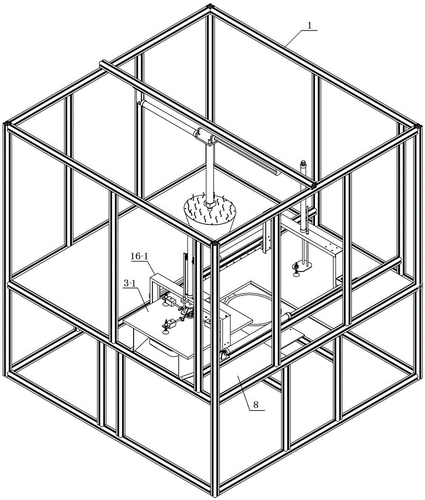
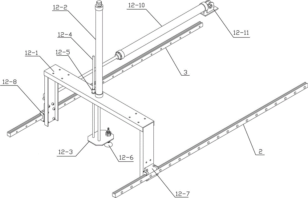
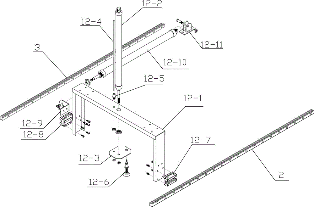
[0032] as attached figure 1 As shown, the present invention includes a frame body 1, a working platform 8 with a long through hole in the middle of the frame body 1, a rectangular material table 3-1 arranged on one side of the working platform 8, and a frame on both sides of the frame body 1. Between the parallel first fetching and feeding sheet linear slide rail 2 and the second fetching and feeding sheet linear slide rail 3, the upper mold linear slide rail 7 arranged on the lower part of the upper beam of the frame body 1, and the upper mold linear slide rail 7 arranged on the first fetching and feeding sheet On the linear slide rail 2 and the second fetching and feeding piece linear slide rail 3 and the corresponding fetching and sending small tablet device and the taking and sending large tablet device, the upper mold and its driving device arranged on the upper mold linear slide rail 7 and The lower mold and its driving device arranged under the long through hole of the ...


PUM


Abstract

The invention relates to an automatic sheet paver of a bulletproof helmet. The automatic sheet paver comprises a frame body, a working platform arranged at one side of the middle in the frame body and provided with a long through hole, a rectangular table arranged at one side of the working platform, first and second sheet taking and feeding linear sliding rails arranged between two side edge frames of the frame body and parallel to each other, an upper mold linear sliding rail arranged on the lower part of an upper cross beam of the frame body, large and small sheet taking and feeding devices arranged between the first and second sheet taking and feeding linear sliding rails and corresponding to each other, an upper mold and driving device thereof which are arranged on the upper mold linear sliding rail, and a lower mold and driving device thereof which are arranged below the long through hole of the working platform, wherein a sheet folding and gathering device and a large sheet folding and gathering place laminating sequence ordering device are arranged on the large sheet taking and feeding device. The automatic sheet paver is used for performing the bulletproof helmet sheet paving operation, so that the sheet paving quality is high, the operation is convenient, and the working efficiency is largely improved.

Description

technical field [0001] The invention relates to an automatic laying machine for bulletproof helmets. Background technique [0002] At present, the production of bulletproof helmets for soldiers or armed police consists of n large pieces (the overall piece is referred to as the large piece) and m small pieces (the oblong pieces added to strengthen the strength of the top of the helmet are referred to as small pieces) Laying sheet composition, large and small pieces are cut from aramid cloth according to size, each large piece has four cutting seams evenly, the whole is in the shape of a fan blade, 4 pieces of large pieces are laid in turn during the production process and then Laying 1 piece of small material, the laying process is all manual spreading, which requires a lot of labor, and such manual laying cannot ensure that each material is accurately spaced at a fixed angle, and the seams cannot be evenly spread out. The unevenness between the paved materials leads to inco...

Claims


Application Information

Patent Timeline
Patent Type & Authority Patents(China)
IPC IPC(8): B29C70/38B29C70/54B29C33/02B29C31/08
CPCB29C31/08B29C33/02B29C70/38B29C70/54B65G47/91
Inventor 马永树李海涛白勇
Owner JIHUA 3502 PROFESSIONAL GARMENT
Learn More