

Liquid crystal display device, method of controlling liquid crystal display device, control program of liquid crystal display device, and storage medium for the control program
A technology of liquid crystal display device and control unit, which is applied to static indicators, nonlinear optics, instruments, etc., and can solve the problems of pixel characteristic change, image afterimage, afterimage, etc.
- Summary
- Abstract
- Description
- Claims
- Application Information
AI Technical Summary
Problems solved by technology
Method used
Image


Examples
Embodiment approach 1
[0036] One embodiment of the present invention will be described.
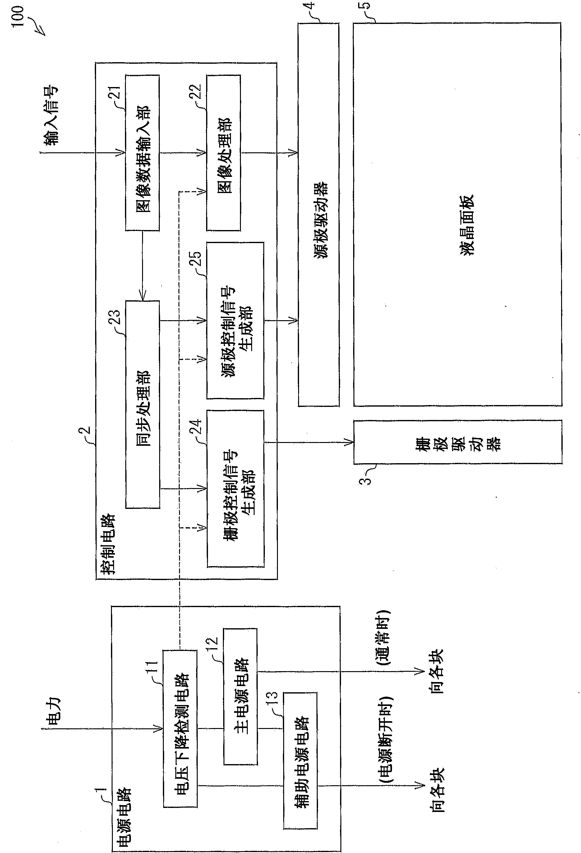
[0037] figure 1 It is an explanatory diagram showing a schematic configuration of the liquid crystal display device 100 of the present embodiment. As shown in the figure, a liquid crystal display device 100 has a power supply circuit 1 , a control circuit (control unit) 2 , a gate driver 3 , a source driver 4 , and a liquid crystal panel 5 .
[0038] The power supply circuit 1 receives power supplied from the outside of the power supply circuit 1 (for example, a commercial power supply, a self-generated power supply, a charging device, etc.), supplies power to each block (each part) of the liquid crystal display device 100, and has a voltage drop detection circuit 11. , The main power supply circuit 12 and the auxiliary power supply circuit 13.
[0039] The voltage drop detection circuit (voltage detection unit) 11 detects that the liquid crystal display device 100 is powered off (power off due to a user's o...
Embodiment approach 2
[0108] Another embodiment of the present invention will be described. In addition, for the sake of convenience of description, parts having the same functions as those described in Embodiment 1 are denoted by the same reference numerals as in Embodiment 1, and description thereof will be omitted.
[0109] Figure 15 It is an explanatory diagram showing an example of control signals of the liquid crystal panel 5 in the liquid crystal display device 100 of the present embodiment, Figure 15 (a) indicates the control signal at the time of normal display, Figure 15 (b) shows a control signal at the time of power-off processing.
[0110] Such as Figure 15 As shown in (a), at the time of normal display, after the gate start pulse GSP becomes high level, the potential of the gate bus line 31 to be selected is controlled at the moment when the gate clock signal GCK is switched from low level to high level. switch to high level. In addition, the gate enable signal GOE is switche...
Embodiment approach 3
[0118] Still another embodiment of the present invention will be described. In addition, for the sake of convenience of explanation, the parts having the same functions as those described in the above-mentioned embodiment are given the same reference numerals as those in the embodiment, and the description thereof will be omitted.
[0119] Figure 16 It is an explanatory diagram showing an example of control signals of the liquid crystal panel 5 in the liquid crystal display device 100 of the present embodiment, Figure 16 (a) indicates the control signal at the time of normal display, Figure 16 (b) shows a control signal at the time of power-off processing.
[0120] Such as Figure 16 As shown in (a), the operation during normal display is the same as that shown in Embodiment 1. Figure 14 The operation of (a) is the same.
[0121] During power-off processing, such as Figure 16 As shown in (b), the period of the gate clock signal GCK is set to be shorter than the peri...
PUM
 Abstract
Description
Claims
Application Information