
Flashlight

A flashlight and power supply technology, applied in the field of lighting tools, can solve the problems of dead calculator battery, single function of flashlight, etc., and achieve the effect of avoiding frequent battery replacement.

Inactive Publication Date: 2014-12-17
QINGDAO ENGAO MOTION CONTROL TECH
View PDF0 Cites 0 Cited by
  • Summary
  • Abstract
  • Description
  • Claims
  • Application Information

AI Technical Summary

Problems solved by technology

[0003] The technical problem to be solved by the present invention is: the singleness of the flashlight function and the inconvenience that the calculator battery is often out of power

Method used


Image

  • Flashlight

Examples


Embodiment Construction

[0008] DETAILED DESCRIPTION OF THE PREFERRED EMBODIMENTS Further details will be given below in conjunction with the drawings.

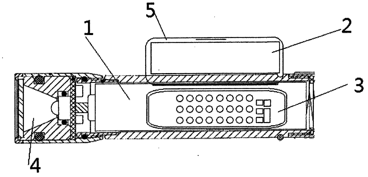
[0009] Electronic balance of the present invention, as figure 1 As shown, it includes a power supply (not shown), a cuboid holding part 1, a lamp cap 4 arranged at one end, a concave groove in the middle of one side of the holding cuboid, and a flip cover 5. The inside of the flip cover is a calculator The display 2 is provided with a calculator function control area 3 inside the concave groove, and the calculator and the flashlight share a power supply. When using the flashlight, the flip cover 5 is closed, and the flashlight is used normally. When the calculator needs to be used, the flip cover is opened, and the operation can be performed through the calculator control area 3 and displayed by the calculator display 2 .

[0010] In summary, the content of the present invention is not limited to the above-mentioned embodiments, people of insight in...


PUM


Abstract

A flashlight comprises a power supply, a cuboid holding portion and a lamp holder arranged at one end of the holding portion. A concave tank is formed in one side of the cuboid holding portion. A clamshell is arranged on the concave tank. A calculator function control area is arranged in the concave tank. The inner side of the clamshell serves as a display screen when the clamshell is opened. A calculator and the flashlight share one power supply. The flashlight with the functions of the calculator is provided, the high utilization frequency of the flashlight is fully used, and meanwhile the trouble that batteries of the calculator are frequently replaced is avoided.

Description

technical field [0001] The invention relates to a lighting tool, in particular to a multipurpose flashlight. Background technique [0002] As a household appliance with high frequency of use, the flashlight has been familiar to people, but the problem of the high usage rate of the flashlight and its single function is becoming more and more prominent. In daily life, people often use calculators, and calculators are often The battery will run out of power. bring a lot of inconvenience. Contents of the invention [0003] The technical problem to be solved by the present invention is: the singleness of the flashlight function and the inconvenience that the calculator battery is often out of power [0004] The present invention solves described technical problem and can realize by adopting following technical scheme: [0005] A flashlight, including a power supply, a rectangular parallelepiped holding part, and a lamp cap arranged at one end of the holding part. There is a ...

Claims


Application Information

Patent Timeline
IPC IPC(8): F21L4/00F21V33/00
Inventor 丁兆捷
Owner QINGDAO ENGAO MOTION CONTROL TECH
Learn More