
A low-power regulated backlight control circuit and a TV

A technology of backlight control and low power consumption, which is applied in the direction of TV, color TV, color TV parts, etc. It can solve the problems of unsatisfied, affecting, and maintaining the stability of the voltage supplied to the main board of the TV, and achieve the effect of improving work efficiency

Active Publication Date: 2017-05-10
GUANGZHOU SHIYUAN ELECTRONICS CO LTD
View PDF3 Cites 0 Cited by
  • Summary
  • Abstract
  • Description
  • Claims
  • Application Information

AI Technical Summary

Problems solved by technology

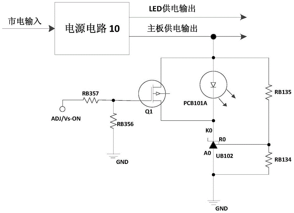
[0005] Due to different application occasions, in the actual production process of LED (Light Emitting Diode, light-emitting diode) TVs, it is often necessary for linear constant current circuits to output different voltage values, and the power supply terminals output to the main board of the TV and the backlight usually belong to the The same transformer, when modulating any one of the power supply output terminals, will inevitably affect the other power supply output terminal
For example, in practice, it is often necessary to adjust the power supply voltage output to the LED light string according to the change in the number of backlight LEDs, and the power supply voltage of the main board of the TV is relatively fixed. At the same time, adaptively maintain the stable voltage supply to the main board of the TV
[0006] In addition, when the existing technology improves the linear constant current circuit, when the power of the backlight LED is turned off, one end of the backlight LED is still connected to a useful electrical device and there is a weak current, so that the weak current is reversely connected to the backlight LED to make the backlight The LED turns on and emits a weak light, which is not allowed in the technical field of TV manufacturing

Method used


Image

  • A low-power regulated backlight control circuit and a TV
  • A low-power regulated backlight control circuit and a TV
  • A low-power regulated backlight control circuit and a TV

Examples


Embodiment Construction

[0062] The following will clearly and completely describe the technical solutions in the embodiments of the present invention with reference to the drawings in the embodiments of the present invention.

[0063] The present invention describes the specific implementation mode by taking the LED TV mainboard and LED backlight as examples. It should be noted that the various circuits provided or improved by the present invention can be applied to various mainboards and LEDs to be powered.

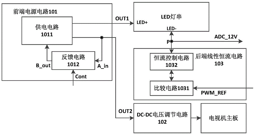
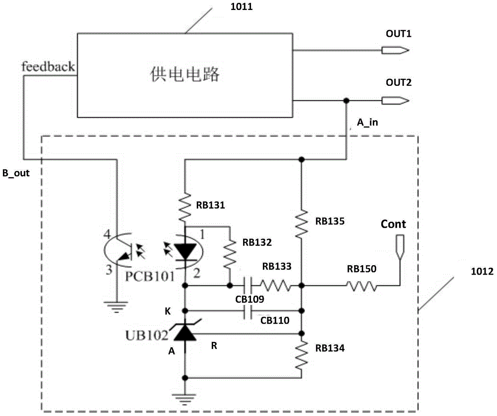
[0064] see figure 2 , is a structural schematic diagram of an embodiment of the low power consumption constant current and voltage stabilization control circuit provided by the present invention.

[0065] In this embodiment, the low power consumption constant current and voltage regulation control circuit includes a front-end power supply circuit 101 , a DC-DC voltage regulation circuit 102 and a rear-end linear constant current circuit 103 .

[0066] The front-end power supply circuit 101 in...


PUM


Abstract

The invention discloses a low-power-consumption stable voltage backlight control circuit. The low-power-consumption stable voltage backlight control circuit comprises a front-end power supply circuit, a DC-DC (Direct Current-Direct Current) voltage regulating circuit, a rear end linear constant current circuit and a voltage detection circuit, wherein the front-end power supply circuit comprises a power supply circuit, a first power supply output end, a second power supply output end and a feedback circuit; the feedback circuit is used for controlling the power supply circuit to adjust voltage values of the first power supply output end and the second power supply output end according to a voltage value of a control signal input end; the DC-DC voltage adjusting circuit is used for adjusting a voltage signal output by the second power supply output end to a fixed voltage signal; the voltage detection circuit is used for switching off current passing through an LED lamp cluster when the LED lamp cluster is closed. The invention further provides a self-adapted power supply adjustable television. According to the technical scheme disclosed by the invention, the output voltage of the circuit can be controlled, supply voltage of a main board is stabilized and a phenomenon that an LED has micro-light when backlight is closed is prevented.

Description

technical field [0001] The invention relates to the technical field of power supply control, in particular to a low power consumption stabilized voltage backlight control circuit and a television set including the low power consumption stabilized voltage backlight control circuit with self-adaptive power supply regulation. Background technique [0002] In the technical field of TV power control, a primary constant current modulation circuit is often used to simultaneously supply power to the main board and the LED backlight. [0003] The constant current modulation circuit is a unit circuit widely used in analog integrated circuits and can be used as a power supply circuit. It is usually equipped with a multi-output transformer, and through the multi-output transformer, one output is drawn out as the output terminal of the LED backlight power supply, and another output is taken out as the power supply output terminal of the main board. In the process of integrating TV compo...

Claims


Application Information

Patent Timeline
Patent Type & Authority Patents(China)
IPC IPC(8): H04N5/44H04N5/63
Inventor 吴永芳刘威河廖武杨达富
Owner GUANGZHOU SHIYUAN ELECTRONICS CO LTD
Learn More