
An indicator lamp with a threshold function

A technology of indicator lights and functions, which is applied to the parts of lighting devices, lighting and heating equipment, electrical components, etc., can solve problems such as dimming, and achieve the effect of increasing stability

Inactive Publication Date: 2018-12-11
江苏稳润光电科技有限公司
View PDF4 Cites 0 Cited by
  • Summary
  • Abstract
  • Description
  • Claims
  • Application Information

AI Technical Summary

Problems solved by technology

[0007] At present, most of the indicator lights have no threshold function. Due to electromagnetic field interference, there will be a faint phenomenon at low voltage.

Method used


Image

  • An indicator lamp with a threshold function
  • An indicator lamp with a threshold function

Examples


Embodiment Construction

[0020] Below in conjunction with accompanying drawing, technical scheme of the present invention is described in further detail:

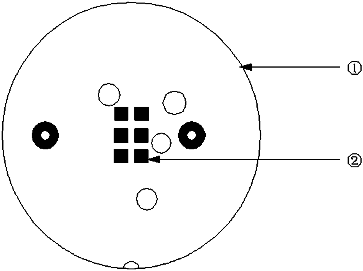
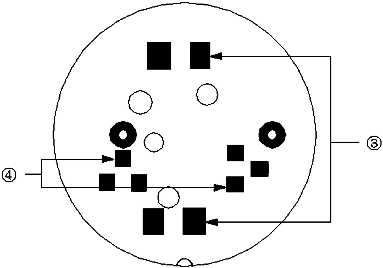
[0021] Such as figure 1 It is the front view of the LED PCB board, figure 2 It is the back view of the PCB board of the indicator light. An indicator light with a threshold function includes a PCB board ①, an LED lamp bead ②, a voltage regulator tube ③, and a rectifier diode ④. Among them, the voltage regulator tube ③ and the rectifier diode ④ are attached to the PCB board ① On the reverse side, the LED lamp beads ② are pasted on the front side of the PCB board ①, and the resistors and capacitors are welded on the back side of the PCB board ①.

[0022] By adopting the above technical solution, in the process of PCB design, two voltage regulator tubes in series are added, each 15V, so that the indicator light will not be dimly lit under the voltage of 30V, and the stability of the use of the indicator light will be increased.

[0023] Those skill...


PUM


Abstract

The invention discloses an indicator lamp with a threshold function, which comprises a PCB board, a resistor, a capacitor, a rectifying diode and two voltage regulating tubes connected in series. Thevoltage regulating tubes and the rectifying diode are stuck on the reverse side of the PCB board, the front side of the PCB board is provided with adhering LED lamp beads, and the resistor and the capacitor are welded on the reverse side of the PCB board. According to the invention, In the PCB design process, two voltage stabilizer tubes are added, so that the indicator lamp has no slight brightness phenomenon at 30V voltage.

Description

technical field [0001] The invention relates to the field of photoelectric technology, in particular to an indicator light with a threshold function. Background technique [0002] LED (Light Emitting Diode), light-emitting diode, is a solid-state semiconductor device that can convert electrical energy into visible light, and it can directly convert electricity into light. The heart of LED is the wafer of a semiconductor, and one end of wafer is attached on a bracket, and one end is negative pole, and the other end connects the positive pole of power supply, and whole wafer is encapsulated by epoxy resin. [0003] Semiconductor wafer is made up of two parts, and a part is P-type semiconductor, and hole occupies an leading position in it, and the other end is N-type semiconductor, and here mainly is electron. But time these two kinds of semiconductors couple together, between them, just form a P-N junction. When electric current acts on this chip by wire time, electron will ...

Claims


Application Information

Patent Timeline
Patent Type & Authority Applications(China)
IPC IPC(8): H05B33/08F21V23/00H05B44/00
CPCF21V23/004H05B45/00
Inventor 汪辉
Owner 江苏稳润光电科技有限公司
Learn More