
A stapler with a binding ruler

A technology of a stapler and a ruler, applied in the directions of staple staple tools, staple tools, manufacturing tools, etc., can solve the problem that the stapler cannot provide a reference for the binding position, etc.

Active Publication Date: 2016-06-08
苏州奕方华知识产权运营有限公司
View PDF7 Cites 0 Cited by
  • Summary
  • Abstract
  • Description
  • Claims
  • Application Information

AI Technical Summary

Problems solved by technology

[0003] The purpose of the present invention is to design a binding ruler on the stapler that can provide the user with a good reference for the binding position, so as to solve the problem that the existing stapler cannot provide a good reference for the binding position

Method used


Image

  • A stapler with a binding ruler
  • A stapler with a binding ruler
  • A stapler with a binding ruler

Examples


Embodiment Construction

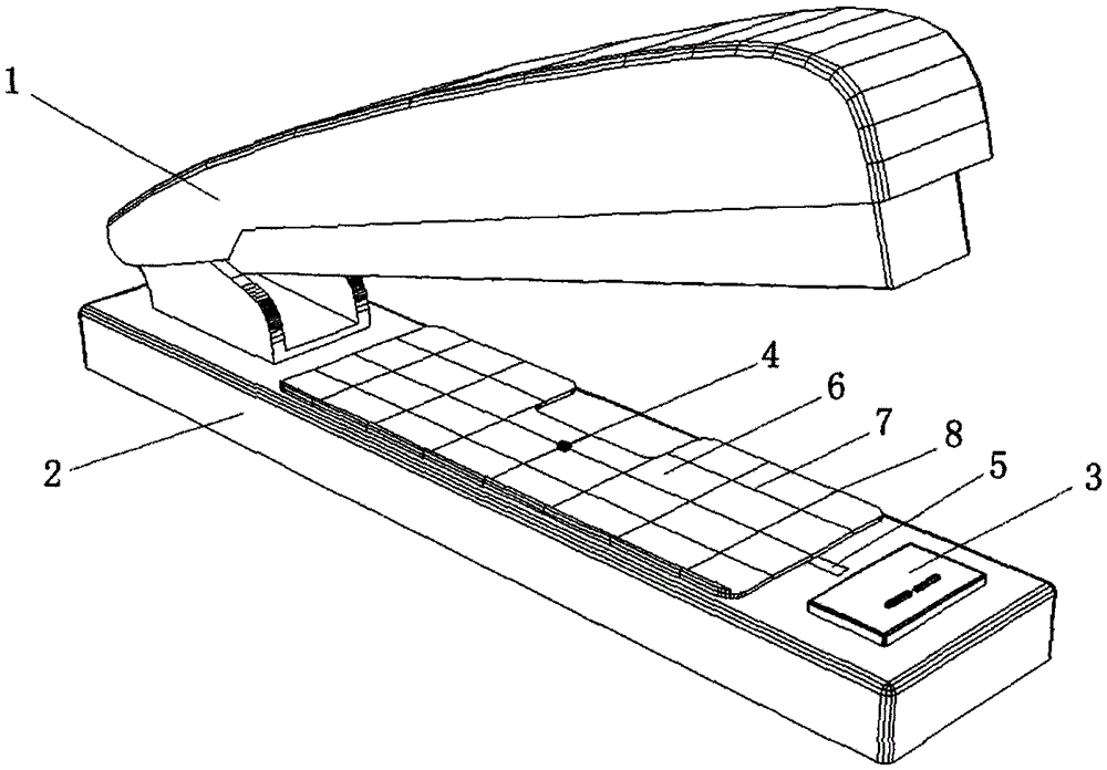
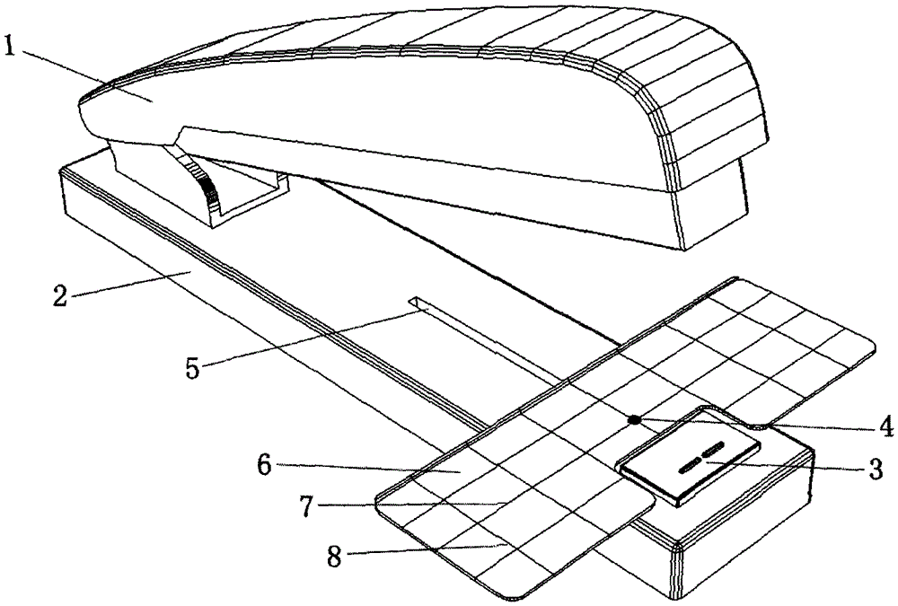
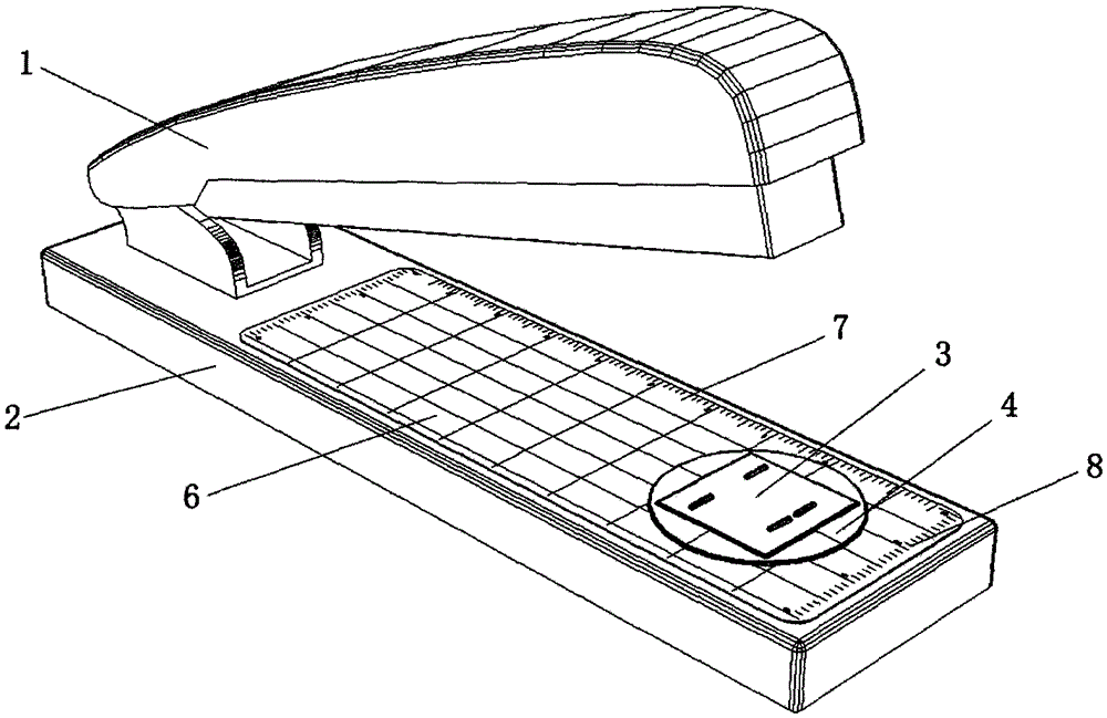
[0010] Control attached figure 1 , 2 , figure 1 is a perspective view of one of the embodiments of the present invention, figure 2 Yes figure 1 Perspective view of the binding ruler in , when swiveled out. Above the stapler base 2 in the figure, a binding scale 6 whose length is greater than the width of the base and whose width is less than or equal to the width of the base is installed. Can slide, there is slide rail 5 on stapler base 2, and rotating shaft 4 is installed on the sliding rail 5, and the position of binding scale 6 can move back and forth along with the sliding of rotating shaft 4; figure 1 It can be seen that when not in use, the binding scale 6 is rotated and stored above the base 2; figure 2 It can be seen that when in use, the binding scale 6 is turned out at 90 degrees along the rotating shaft 4 to form a length greater than the width of the base, which plays a role in supporting the paper during binding and utilizes the scale line to provide a bind...


PUM


Abstract

The invention relates to a stapler provided with a stapling scale. The stapling scale, whose length is greater than the width of a base and width is smaller than or equal to the width of the base, is mounted above the base of the stapler, and is connected to the base through axial rotation of a rotating shaft; when the stapler is not used, the stapling scale is rotated to be accommodated above the base; when the stapler is used, the stapling scale is rotated out by 90 degrees along the rotating shaft, so that the length of the stapling scale is greater than the width of the base, and the stapling scale plays a part in supporting papers and uses scale marks to provide the stapling position reference in stapling; transverse scale marks and longitudinal scale marks are arranged on the stapling scale; the transverse scale marks provide the distance reference and the parallel reference for a stapling line and the side edge of the paper to a binder, so that the distance from the stapling line to the side edge of the paper accords with the stapling requirement, and stapling nails are parallel to the side edge of the stapled paper; and the longitudinal scale marks on the stapling scale provide the distance reference for a stapling position and the upper and lower edges of the paper to the binder, so that the distance from the stapling position to the upper and lower edges of the paper accords with the stapling requirement.

Description

technical field [0001] The present invention relates to a stapler with a binding scale, which is installed on the base of the existing stapler and can be rotatably stored on the base. When in use, the length of the 90-degree rotation from the base is greater than the width of the base. Binding ruler to solve the problem that the existing staplers lack effective reference when binding, resulting in two staples having different distances from the page edge, not parallel to the page edge, two nails not parallel to each other, and not on the same binding line And other issues. Background technique [0002] The stapler is mainly composed of a binding mechanism, a base, and a staple deformer. At present, most common staplers are not designed with a binding scale that can serve as a reference for the binding position, and a small number of them are designed with a binding position baffle. The existing stapler has the problem that the baffle is too short to play a good reference ro...

Claims


Application Information

Patent Timeline
Patent Type & Authority Patents(China)
IPC IPC(8): B25C5/02B25C7/00
CPCB25C5/02B25C7/00
Inventor 王佐良
Owner 苏州奕方华知识产权运营有限公司
Learn More