
A peak power prediction method for power batteries

A technology of peak power and prediction method, which is applied in the direction of measuring electric power, measuring electricity, electric vehicles, etc., can solve the problems that cannot be improved, such as inaccurate power estimation, poor real-time performance, and large error of the first-order RC model.

Active Publication Date: 2017-03-01
HARBIN INST OF TECH
View PDF6 Cites 0 Cited by
  • Summary
  • Abstract
  • Description
  • Claims
  • Application Information

AI Technical Summary

Problems solved by technology

[0003] Most of these methods use the first-order RC equivalent circuit model of the battery, and use SOC, terminal voltage, and current as the limiting conditions for peak power prediction. Early power prediction methods use offline battery model parameter data to complete the prediction of battery output / feedback peak power. , but as the battery ages or changes in temperature, working conditions and other environments, the model parameters will also change accordingly. Therefore, the power estimation method based on offline model parameter data is less reliable;
[0004] In the latest published papers, the battery model parameter data is obtained online by the parameter estimation method, which can effectively improve the accuracy of estimation, but due to the large error of the first-order RC model itself, the power prediction can only be limited to a short period of time. Effective
[0005] In order to reduce the discretization error of the state equation when it is used for power prediction, a smaller discretization time interval (such as taking the time interval as 1s or 0.1s) is used in the paper. The peak power prediction value at 10s or the prediction value at 60s, the disadvantage of this method is that there are a lot of recursive calculations, and the real-time performance is poor
In addition, this method cannot improve the problem of inaccurate power estimation caused by the model's own error.

Method used


Image

  • A peak power prediction method for power batteries
  • A peak power prediction method for power batteries
  • A peak power prediction method for power batteries

Examples


specific Embodiment approach 1

[0139] Specific Embodiments 1. A peak power prediction method for a power battery,

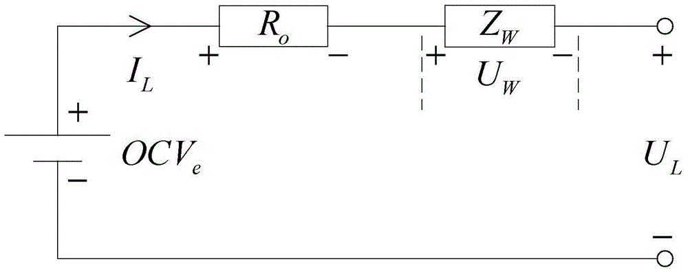
[0140] The invention discloses a method for estimating the peak value of a power battery. The method includes two parts: A is based on the simplified electrochemical impedance spectrum equivalent circuit model and online parameter estimation of the fractional joint Kalman filter; B is based on the zero state response and zero Input Response Decomposition for Battery Peak Power Prediction Method.

[0141] The specifics of the method are: a battery power prediction method based on a simplified electrochemical impedance spectroscopy equivalent circuit model, fractional joint Kalman filter, zero-state response and zero-input response decomposition. It is achieved by the following steps:

[0142] Step 1. According to the test results of the electrochemical impedance spectroscopy of the battery, since in the impedance spectroscopy, the equivalent circuit model of the electrochemical impedance spect...


PUM


Abstract

The invention discloses a peak power prediction method for a power battery, relates to a peak power prediction technology for the power battery, and aims to improve the peak power prediction accuracy for the power battery. The method disclosed by the invention comprises the following two parts: A, parameter online estimation based on a simplified electrochemical impedance spectrum equivalent circuit model and fractional order combined kalman filtering; B, a battery peak power prediction method based on decomposition of zero-state response and zero-input response. According to the invention, the simplified impedance spectrum model comprising a fractional order component is selected as a reference model for the battery peak power prediction, so that the peak power prediction method based on the model not only can accurately predict short-time peak output power of the battery, but also can accurately predict the peak power output capacity of the battery within a longer time period. The peak power prediction method is suitable for online peak power prediction of an electric car.

Description

technical field [0001] The invention relates to a peak power prediction technology of a power battery. Background technique [0002] Domestic patents disclose less content about battery peak power prediction methods, and domestic and foreign papers and periodicals have some methods for power battery peak power prediction. [0003] Most of these methods use the first-order RC equivalent circuit model of the battery, and use SOC, terminal voltage, and current as the limiting conditions for peak power prediction. Early power prediction methods use offline battery model parameter data to complete the prediction of battery output / feedback peak power. , but as the battery ages or changes in temperature, working conditions and other environments, the model parameters will also change accordingly. Therefore, the power estimation method based on offline model parameter data is less reliable; [0004] In the latest published papers, the battery model parameter data is obtained online...

Claims


Application Information

Patent Timeline
Patent Type & Authority Patents(China)
IPC IPC(8): G01R31/36G01R21/00
Inventor 朱春波李晓宇魏国裴磊
Owner HARBIN INST OF TECH
Learn More