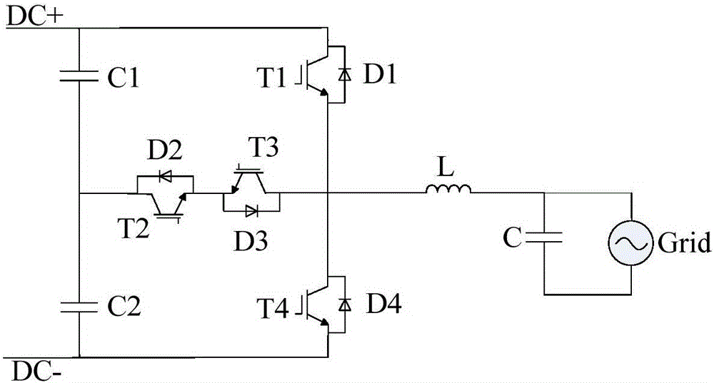
A three-level wave-by-wave current limiting control method and system
A technology of wave-by-wave current limiting and control method, applied in electrical components, conversion devices for converting AC power input to DC power output, and output power, etc. , to achieve the effect of good current waveform quality, smooth output current and avoiding false current limiting
- Summary
- Abstract
- Description
- Claims
- Application Information
AI Technical Summary
Problems solved by technology
Method used
Image
Examples
Embodiment 1
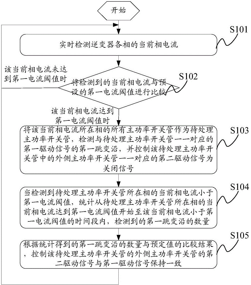
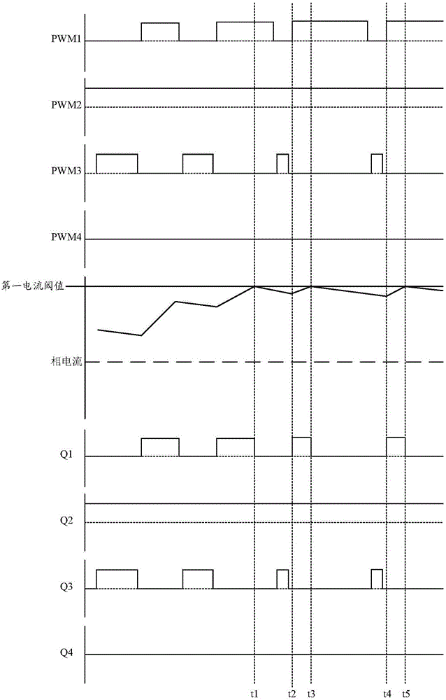
[0063] like figure 2 As shown, it is a schematic flow chart of an embodiment of a three-level wave-by-wave current limiting control method of the present invention, combined with image 3 The timing diagram of the three-level wave-by-wave current limiting control method shown in the embodiment of the present invention, the control method may include the following steps:
[0064] Step S101: Detect the current phase current of each phase of the inverter in real time.
[0065] In practical applications, the current detection circuit in the system can be used to detect the current current of each phase of the system, so as to subsequently determine whether the inverter has overcurrent. Wherein, the number of current detection circuits in this embodiment may depend on the output phases of the system. For a three-phase inverter, three current detection circuits are required to detect the overcurrent signals of the phases respectively.
[0066] Of course, a DSP (Digital Signal Pro...
Embodiment 2
[0087] like Figure 5 As shown, it is a schematic flow chart of another embodiment of the three-level wave-by-wave current limiting control method of the present invention, and the method may include the following steps:
[0088] Step S201: Detect the current phase current of each phase of the inverter in real time.
[0089] Step S202: Comparing the current phase current with preset first current threshold and second current threshold respectively.
[0090] Wherein, when the current phase current is less than the first current threshold value, it means that the inverter does not have an overcurrent, and it will return to step S201 to continue execution.
[0091] Step S203: When the current phase current is greater than the first current threshold and less than the second current threshold, use all the main power switching tubes of the phase where the current phase current is located as the main power switching tubes to be processed, and detect the The rising edge of the firs...
Embodiment 3
[0106] like Figure 7 As shown, it is a schematic structural diagram of an embodiment of a three-level wave-by-wave current limiting control system embodiment of the present invention, and the system may include:
[0107] The DSP chip 301, the wave-by-wave current limiting processing device 302, the main power drive circuit 303 and the main power circuit 304 connected in sequence, and the first overcurrent signal judging circuit 305 connected with the wave-by-wave current limiting processing device 302 are connected with the The current detection circuit 306 connected to the first overcurrent signal judging device 305 is respectively connected to the port corresponding to the outer power switch tube of the main power circuit 304 in the DSP chip 301, and the wave-by-wave current limiting processing device 302 The connected first drive signal detection device 307, wherein:
[0108] The DSP chip 301 is configured to generate first driving signals corresponding to the main power ...
PUM
 Abstract
Description
Claims
Application Information
 - R&D
- Intellectual Property
- Life Sciences
- Materials
- Tech Scout
- Unparalleled Data Quality
- Higher Quality Content
- 60% Fewer Hallucinations
Browse by: Latest US Patents, China's latest patents, Technical Efficacy Thesaurus, Application Domain, Technology Topic, Popular Technical Reports.
© 2025 PatSnap. All rights reserved.Legal|Privacy policy|Modern Slavery Act Transparency Statement|Sitemap|About US| Contact US: help@patsnap.com


