Three-level wave-by-wave current limiting control method and system

A wave-by-wave current limiting and control method technology, applied to electrical components, AC power input conversion to DC power output, output power conversion devices, etc., can solve large voltage difference, reduce the quality of current waveform, and three-level inverter The problem of small inductance of the reactor and the reactor is eliminated, and the output current is smooth and the quality of the current waveform is good.

Active Publication Date: 2015-01-07
SUNGROW POWER SUPPLY CO LTD
View PDF4 Cites 17 Cited by
  • Summary
  • Abstract
  • Description
  • Claims
  • Application Information

AI Technical Summary

Problems solved by technology

[0004] However, due to the small inductance of the three-level inverter reactor, the output voltage of the bridge arm of the over-current phase is +E / 2 or -E / 2 during the switching cycle of turning off all the main power switch tubes of the over-current phase, The output voltage will generate a large voltage difference on the reactance, which will cause a large drop in the current on the reactance, reduce the quality of the current waveform, and easily generate resonance

Method used


Image

  • Three-level wave-by-wave current limiting control method and system
  • Three-level wave-by-wave current limiting control method and system
  • Three-level wave-by-wave current limiting control method and system

Examples


Embodiment 1

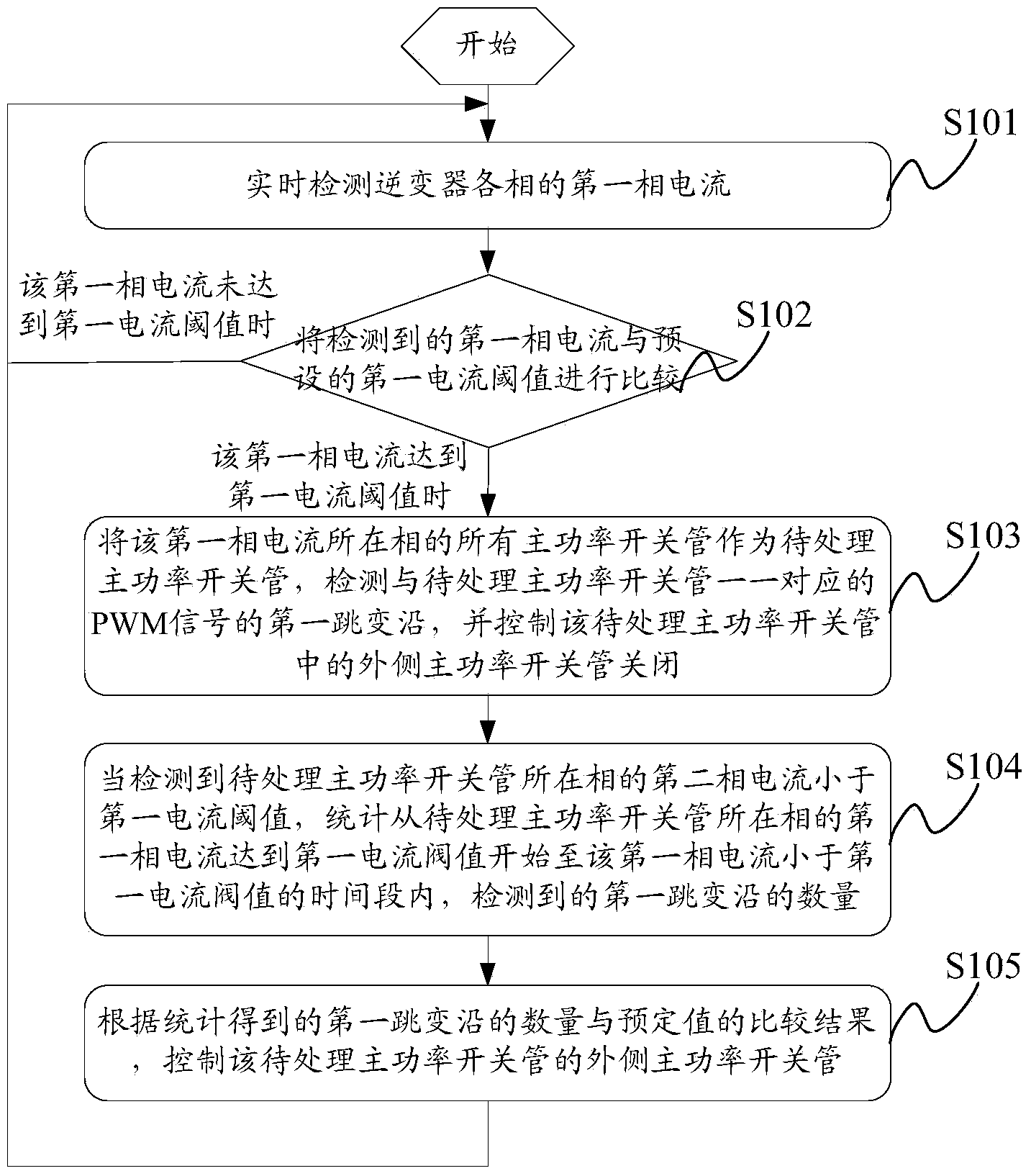
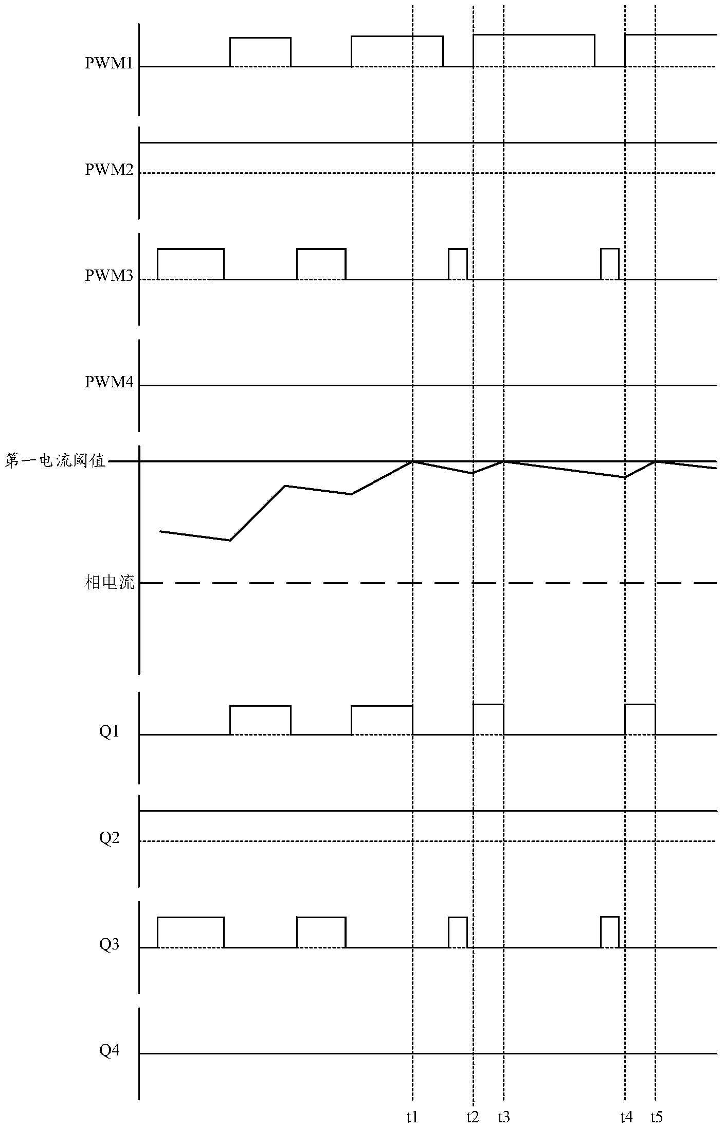
[0056] Such as figure 2 As shown, it is a schematic flow chart of an embodiment of a three-level wave-by-wave current limiting control method of the present invention, combined with image 3 The timing diagram of the three-level wave-by-wave current limiting control method shown in the embodiment of the present invention, the control method may include the following steps:

[0057] Step S101: Real-time detection of the first phase current of each phase of the inverter.

[0058] In practical applications, the current detection circuit in the system can be used to detect the current current of each phase of the system, that is, the first phase current, so as to subsequently determine whether the inverter has overcurrent based on this. Wherein, the number of current detection circuits in this embodiment may depend on the output phases of the system. For a three-phase inverter, three current detection circuits are required to detect the overcurrent signals of the phases respecti...

Embodiment 2

[0080] Such as Figure 5 As shown, it is a schematic flow chart of another embodiment of the three-level wave-by-wave current limiting control method of the present invention, and the method may include the following steps:

[0081] Step S201: Real-time detection of the first phase current of each phase of the inverter.

[0082] Step S202: Compare the first phase current with preset first current threshold and second current threshold respectively.

[0083] Wherein, when the first phase current is less than the first current threshold value, it means that the inverter does not have overcurrent, and it will return to step S201 to continue execution.

[0084] Step S203: When the first phase current is greater than the first current threshold and less than the second current threshold, use all the main power switching tubes of the phase where the first phase current is located as the main power switching tubes to be processed, and detect the Processing the rising edges of the P...

Embodiment 3

[0099] Such as Figure 7 As shown, it is a schematic structural diagram of an embodiment of a three-level wave-by-wave current limiting control system embodiment of the present invention, and the system may include:

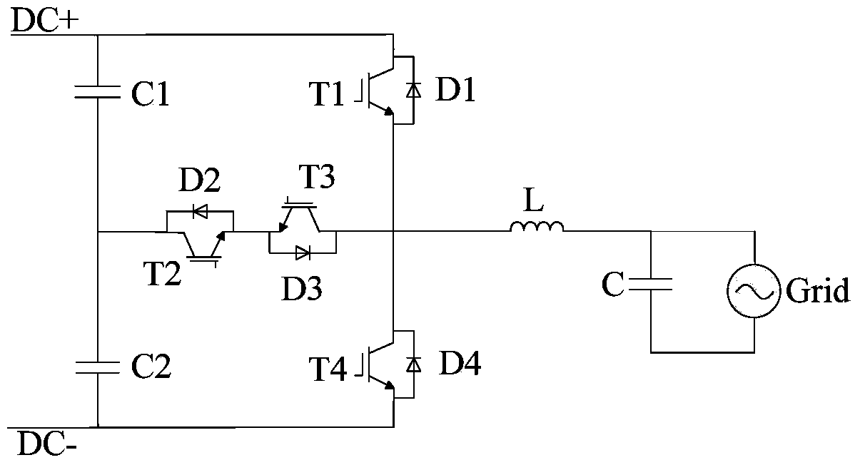
[0100] The DSP chip 301, the wave-by-wave current limiting processing device 302, the main power drive circuit 303 and the main power circuit 304 connected in sequence, and the first overcurrent signal judging circuit 305 connected with the wave-by-wave current limiting processing device 302 are connected with the The current detection circuit 306 connected to the first overcurrent signal judging device 305 is respectively connected to the port corresponding to the outer power switch tube of the main power circuit 304 in the DSP chip 301, and the wave-by-wave current limiting processing device 302 The connected PWM signal detection device 307, wherein:

[0101] The DSP chip 301 is used to generate PWM signals corresponding one-to-one to the main power switch tub...


PUM


Abstract

The invention provides a three-level wave-by-wave current limiting control method and system. The method comprises the steps that when the detected first-phase current of a main power switch tube in each phase of an inverter reaches a preset first current threshold value, the main power switch tubes of the phases where the first-phase currents are located are regarded as main power switch tubes to be processed; outer main power switch tubes in the main power switch tubes to be processed are controlled to be switched off till it is detected that the first-phase currents in the corresponding phases are smaller than the preset first current threshold value; according to comparison between the number, obtained through statistics, of the first jump edges of PWM signals detected in the overcurrent period and a preset value, an appropriate time is determined for controlling the outer main power switch tubes in the main power switch tubes to be processed in the corresponding phases to be consistent with input. Thus, the output current of an electric reactor of the inverter can be gentle and will not substantially drop suddenly, the waveform quality of the current is good in the wave-by-wave current limiting period, resonance is avoided, a system is more reliable, faulty current limiting in the current limiting quitting process is avoided, and the working efficiency of the system is improved.

Description

technical field [0001] The present invention mainly relates to the field of wave-by-wave current limiting, and more specifically relates to a three-level wave-by-wave current limiting control method and system. Background technique [0002] After research, it is found that during the operation of the inverter, overcurrent phenomena usually occur due to reasons such as too small load impedance and bridge arm short-circuit, which affect the safe and reliable operation of the system. [0003] In order to realize the over-current protection of the inverter, in the prior art, when an over-current signal is detected, all main power switches of the inverter over-current phase are usually turned off, and when the over-current signal disappears and the detected When the PWM (Pulse-Width Modulation, pulse width modulation) signal of the main power switch tube enters the next switching period, the above-mentioned closed main power switch tube is turned on again. [0004] However, due ...

Claims


Application Information

Patent Timeline
IPC IPC(8): H02M7/483
CPCH02M1/126H02M7/483
Inventor 余鸿张浩叶亮
Owner SUNGROW POWER SUPPLY CO LTD
Why Eureka
Try Eureka