
Inverter brushless excitation system for separated intermediate-frequency transformer based on IGBT (Insulated Gate Bipolar Translator) technology
An excitation system, a separate technology, applied in the field of excitation system, can solve the problems of unable to routinely detect the excitation circuit of the generator, increase the length of the generator shaft, and easily generate vibration for the exciter, so as to reduce the overall size and weight, reduce the The effect of low cost and small size
- Summary
- Abstract
- Description
- Claims
- Application Information
AI Technical Summary
Problems solved by technology
Method used
Image

Examples
Embodiment Construction
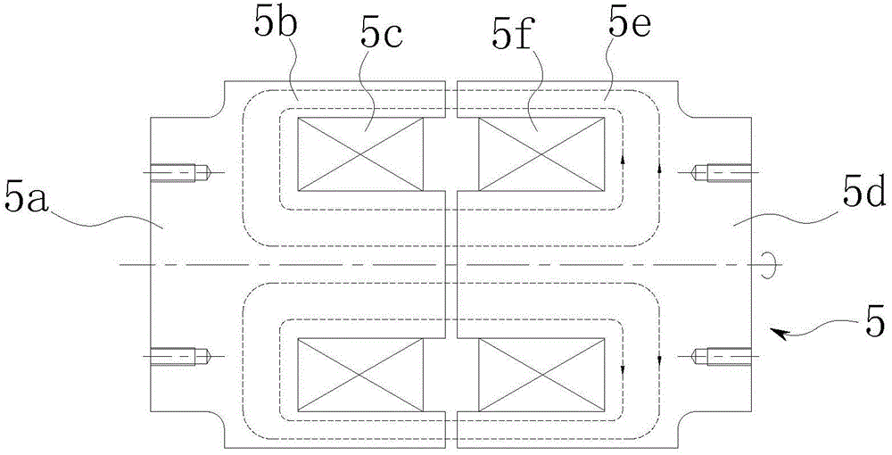
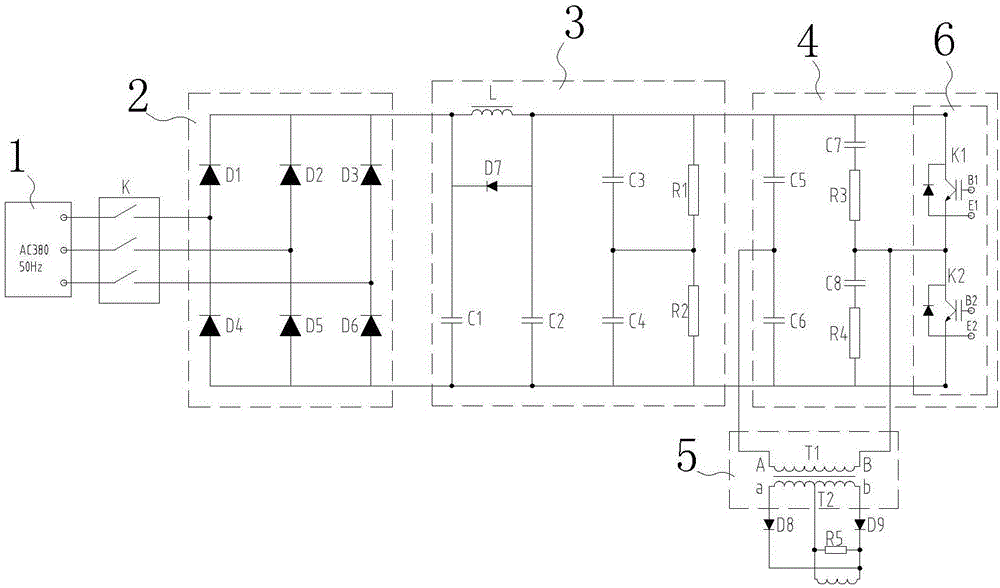
[0032] refer to figure 1 and figure 2 As shown, a separated intermediate frequency transformer inverter brushless excitation system based on IGBT technology of the present invention includes a power frequency AC power supply 1, the power frequency AC power supply 1 is connected with a rectifier module 2, and the DC output from the rectifier module 2 An LC filter circuit 3 and an IGBT inverter circuit 4 are sequentially connected between the positive and negative poles of the power supply. The IGBT inverter circuit 4 is connected to an intermediate frequency separated resolver 5 , which is relatively fixed to the generator stator The primary coupling part 5a, the primary magnetic core 5b arranged on the primary coupling part 5a, the primary coil 5c wound on the primary magnetic core 5b, the secondary coupling part 5d coaxially rotating with the generator rotor, and the secondary coupling part 5d arranged on the secondary The secondary magnetic core 5e on the coupling part 5d ...
PUM
 Abstract
Description
Claims
Application Information