Power detection circuit
A technology for detecting circuits and power, which is applied in the direction of measuring electrical variables, measuring electrical power, and measuring electrical power through current/voltage, etc. It can solve the problems that it is inconvenient for users to check or correct the power supply, and the power supply power of electronic products cannot be detected. , to achieve the effect of power correction
- Summary
- Abstract
- Description
- Claims
- Application Information
AI Technical Summary
Problems solved by technology
Method used
Image

Examples
Embodiment Construction
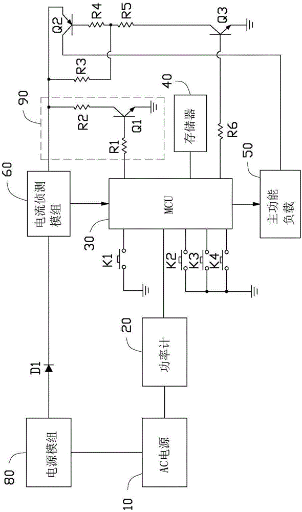
[0022] see figure 1 , in a first preferred embodiment of the present invention, a power detection circuit is used to detect the power consumption of an electronic device, which includes a power meter 20, an MCU (Micro Control Unit, micro control unit) 30, A memory 40 connected to the MCU 30 , a main function load 50 , a current detection module 60 , a power supply module 80 and a calibration circuit 90 connected to the MCU 30 . The power supply module 80 is connected to an AC (alternating current, alternating current) power source 10 , and can convert the AC voltage output by the AC power source 10 into a DC voltage for each load in the circuit. The power supply module 80 includes a bridge rectifier circuit, a PFC (Power Factor Correction, power factor correction) module and an AC-to-DC (AC to DC) conversion module. The memory 40 is used to store the data received by the MCU 30, which is convenient for invoking and querying historical data. In one embodiment, all components ...
PUM
 Abstract
Description
Claims
Application Information
 - Generate Ideas
- Intellectual Property
- Life Sciences
- Materials
- Tech Scout
- Unparalleled Data Quality
- Higher Quality Content
- 60% Fewer Hallucinations
Browse by: Latest US Patents, China's latest patents, Technical Efficacy Thesaurus, Application Domain, Technology Topic, Popular Technical Reports.
© 2025 PatSnap. All rights reserved.Legal|Privacy policy|Modern Slavery Act Transparency Statement|Sitemap|About US| Contact US: help@patsnap.com