Insert clamping device for vamp color spraying

A technology of color spraying and shoe uppers, applied in the direction of shoemaking machinery, applications, footwear, etc., to ensure personal safety and health, reduce production costs, and improve production efficiency

Inactive Publication Date: 2015-04-01
HUANGHE S & T COLLEGE +1
View PDF4 Cites 0 Cited by
  • Summary
  • Abstract
  • Description
  • Claims
  • Application Information

AI Technical Summary

Problems solved by technology

[0002]At present, in the shoe industry, due to the similar appearance of shoes, the main difference is that the specifications and sizes of the shoes are different, and the shoes have strict specification requirements. Therefore, the shoes The production is generally carried out in the form of an assembly line. The materials for shoemaking are placed on pallets or brackets, and the pallets or brackets move along the transportation channel. Shoemaking production is generally mass-produced, but the supporting area of ​​the pallets or brackets is limited. The transportation capacity is limited, which cannot meet the needs of the shoe industry. At the same time, shoe-making employees have to pick and place shoe parts from pallets or brackets, which further reduces the production efficiency of shoe-making. The code does not correspond to the material, which increases the number of defective products and causes unnecessary economic losses
At the same time, when spraying color on the upper of the shoe, it is necessary to spray color on all four sides of the shoe. This requires the operator to manually rotate the shoe after spraying one surface, and spray color on the four sides of the shoe. Manual rotation is inefficient. At the same time, when the paint is still wet, the newly sprayed upper will be damaged when rotating. At the same time, the spraying environment is extremely poor. The mist paint will fill the construction space and will be inhaled by the operators, affecting the health of the workers.

Method used


Image

  • Insert clamping device for vamp color spraying
  • Insert clamping device for vamp color spraying

Examples


Embodiment Construction

[0026] The present invention will be further described in detail below in conjunction with the accompanying drawings.

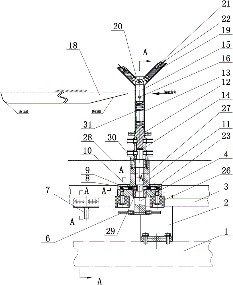
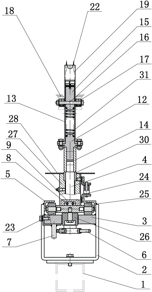
[0027] Such as figure 1 , figure 2 As shown, a kind of inserting and holding device for upper color spraying includes a frame 1, a lower rail bracket 2 is arranged on the frame 1, a lower rail 3 is fixed on the lower rail bracket 2, and a shoe fork shaft 4 is worn on the plug. In the frame bottom plate 23, a lower sliding copper sleeve 29 is arranged between the shoe fork shaft 4 and the frame bottom plate 23, and lower rollers 25 are arranged on both sides of the frame bottom plate 23, and the lower rollers 25 move along the lower guide rail 3, thereby driving the frame bottom plate 23 Moving along the lower guide rail 3, guide wheels 26 are arranged at the front and rear ends of the frame base plate 23, the guide wheels 26 are arranged in the guide groove in the middle of the lower guide rail 3, the middle part of the shoe fork shaft 4 is installed in th...


PUM


Abstract

The invention relates to an insert clamping device for vamp color spraying. A rack is provided with a lower guide rail bracket; the lower guide rail bracket is fixedly provided with a lower guide rail; the middle of a shoe fork shaft is provided with a moving mechanism; the moving mechanism drives the shoe fork shaft to move along the lower guide rail; the upper end of the shoe fork shaft is connected with the lower end of an insert clamping mechanism; the upper end of the insert clamping mechanism is used for clamping a shoe product; the lower part of the shoe fork shaft is provided with a steering mechanism; the steering mechanism drives the shoe fork shaft to rotate for 90 degrees each time. According to the insert clamping device,a clamping-type shoe product conveying mode is designed, automatic clamping and automatic unloading are achieved, and the insert clamping device can rotate for 90 degrees each time, so that a color spraying operation for four surfaces of a shoe product is convenient; the color spraying operation is performed on the shoe product by virtue of a color spraying machine, so that automatic continuous production of shoe products is convenient, workers are not required to take, put and overturn parts manually, the production efficiency is improved, the production cost is lowered, the shoe products are automatically rotated, color spraying is performed by virtue of the color spraying machine, manual operation is not needed, the workers are away from a color spraying environment, the personal safety and health are ensured.

Description

[0001] Technical field: [0002] The invention belongs to the technical field of equipment for shoe production and processing, and in particular relates to an inserting and holding device for shoe upper color spraying in a shoe production line. [0003] Background technique: [0004] At present, in the shoe-making industry, due to the similar appearance of shoes, the main difference is that the specifications and sizes of the shoes are different, and the shoes have strict specification requirements. On the pallet or bracket, the pallet or bracket moves along the transportation channel. Shoemaking production is generally mass production, but the supporting area of ​​the pallet or bracket is limited, and the transportation capacity is limited, which cannot meet the needs of shoe production. At the same time, the manufacturing Shoe workers also need to pick and place shoe parts from pallets or brackets, which further reduces the production efficiency of shoemaking. economic lo...

Claims


Application Information

Patent Timeline
Patent Type & Authority Applications(China)
IPC IPC(8): A43D95/06
Inventor 付志豪孙敏王锦燕马骁付若愚
Owner HUANGHE S & T COLLEGE
Why Eureka
Try Eureka