Dehumidifier, and control method and control device thereof

A control method and technology of a control device, which are applied in heating and ventilation control systems, heating methods, mechanical equipment, etc., can solve the problems of long defrosting cycle time, poor defrosting effect, and low dehumidification capacity, so as to improve the dehumidification capacity. , The effect of dehumidification is remarkable, and the effect of improving the speed of defrosting

Active Publication Date: 2015-04-08
GD MIDEA AIR-CONDITIONING EQUIP CO LTD
View PDF5 Cites 3 Cited by
  • Summary
  • Abstract
  • Description
  • Claims
  • Application Information

AI Technical Summary

Problems solved by technology

[0002] At present, the range of dehumidifier products is more and more widely used. Among them, in some regions of high latitude in Europe and North America, the working conditions of dehumidifiers are relatively low and medium. In this environment, the air dew point temperature is generally close to zero or even lower than zero. Therefore, after the dehumidifier runs for a certain period of time, the evaporator of the dehumidifier will frost, and the frost will become thicker and thicker after a long time, and finally freeze, resulting in a large thermal resistance. At this time, the dehumidifier basically cannot continue to dehumidify. In this case, if the dehumidifier continues to run without defrosting, it will cause waste of electric energy. Therefore, the dehumidifier needs to perform defrosting work in this case
[0003] There are many defrosting methods for existing dehumidifiers, but the mainstream products of household dehumidifiers basically stop the compressor, and the fan continues to blow to defrost. This defrosting method is relatively traditional, but the defrosting speed is relatively slow and the defrosting The frost cycle time is long, resulting in low dehumidification capacity on average in the overall operation of the dehumidifier, and poor defrosting effect

Method used


Image

  • Dehumidifier, and control method and control device thereof
  • Dehumidifier, and control method and control device thereof
  • Dehumidifier, and control method and control device thereof

Examples


Embodiment Construction

[0031] Embodiments of the present invention are described in detail below, examples of which are shown in the drawings, wherein the same or similar reference numerals designate the same or similar elements or elements having the same or similar functions throughout. The embodiments described below by referring to the figures are exemplary only for explaining the present invention and should not be construed as limiting the present invention.

[0032] The following disclosure provides many different embodiments or examples for implementing different structures of the present invention. To simplify the disclosure of the present invention, components and arrangements of specific examples are described below. Of course, they are only examples and are not intended to limit the invention. Furthermore, the present invention may repeat reference numerals and / or letters in different instances. This repetition is for the purpose of simplicity and clarity and does not in itself indicat...


PUM


Abstract

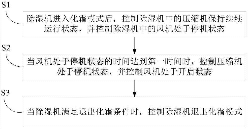
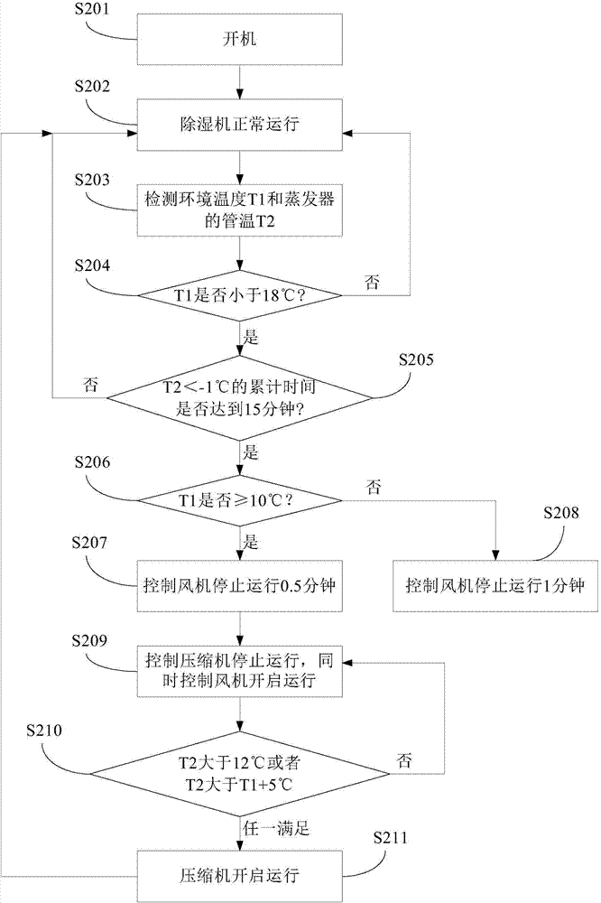
The invention discloses a control method of a dehumidifier. The control method comprises the following steps: after the dehumidifier enters a defrosting mode, controlling a compressor in the dehumidifier to keep a continuous running state, and controlling a fan in the dehumidifier to be in an off state; when the off-state time of the fan reaches a first time, controlling the compressor to be in the off state and controlling the fan to be in an on state; when the dehumidifier meets a defrosting-exiting condition, controlling the dehumidifier to exit from the defrosting mode. When the control method of the dehumidifier controls the defrosting of the dehumidifier, the defrosting speed of the dehumidifier can be increased and the dehumidifying amount of the dehumidifier under a low-temperature or medium-temperature working condition is enhanced, so that the dehumidifying effect of the dehumidifier is significant. The invention further discloses a control device of the dehumidifier and the dehumidifier.

Description

technical field [0001] The invention relates to the technical field of dehumidifiers, in particular to a control method for a dehumidifier, a control device for a dehumidifier, and a dehumidifier with the control device. Background technique [0002] At present, the range of dehumidifier products is more and more widely used. Among them, in some regions of high latitude in Europe and North America, the working conditions of dehumidifiers are relatively low and medium. In this environment, the air dew point temperature is generally close to zero or even lower than zero. Therefore, after the dehumidifier runs for a certain period of time, the evaporator of the dehumidifier will frost, and the frost will become thicker and thicker after a long time, and finally freeze, resulting in a large thermal resistance. At this time, the dehumidifier basically cannot continue to dehumidify. In this case, if the dehumidifier continues to run without defrosting, it will cause waste of elect...

Claims


Application Information

Patent Timeline
Patent Type & Authority Applications(China)
IPC IPC(8): F24F11/00
CPCF24F11/70
Inventor 邓秦波邓海钊
Owner GD MIDEA AIR-CONDITIONING EQUIP CO LTD
Why Eureka
Try Eureka