Drain pump

A drainage pump and pump casing technology, applied in the direction of pumps, pump components, pump devices, etc., can solve the problems of unsmooth discharge, residual water, unsatisfactory sanitary environment, etc., and achieve the effect of eliminating bad conditions.

CN104514728AActive Publication Date: 2015-04-15FUJIKOKI MFG CO LTD
9 Cites 6 Cited by

Patent Information

Authority / Receiving Office
CN · China
Patent Type
Applications(China)
Current Assignee / Owner
Publication Date
2015-04-15

Smart Images

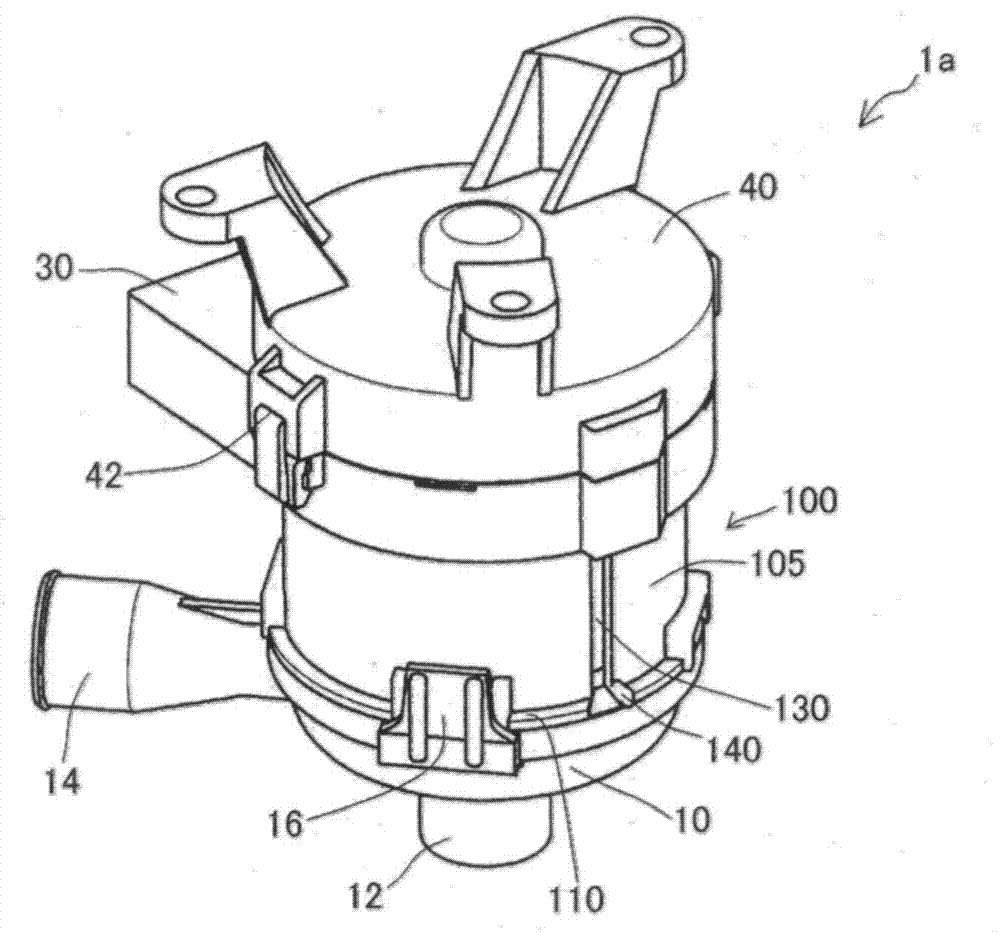
  • Figure 1
    Figure 1
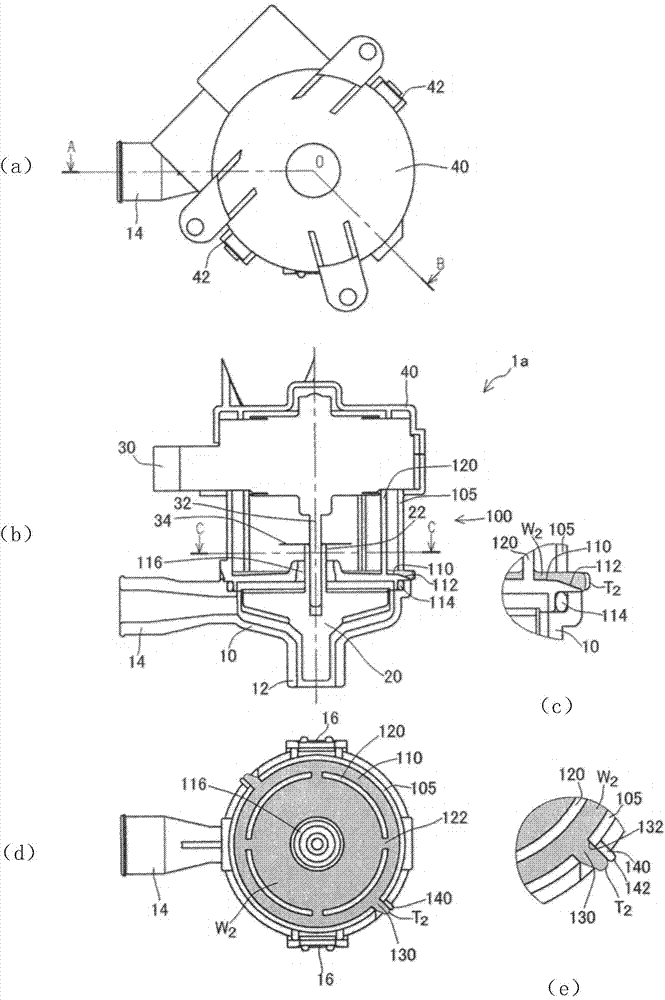
  • Figure 2
    Figure 2
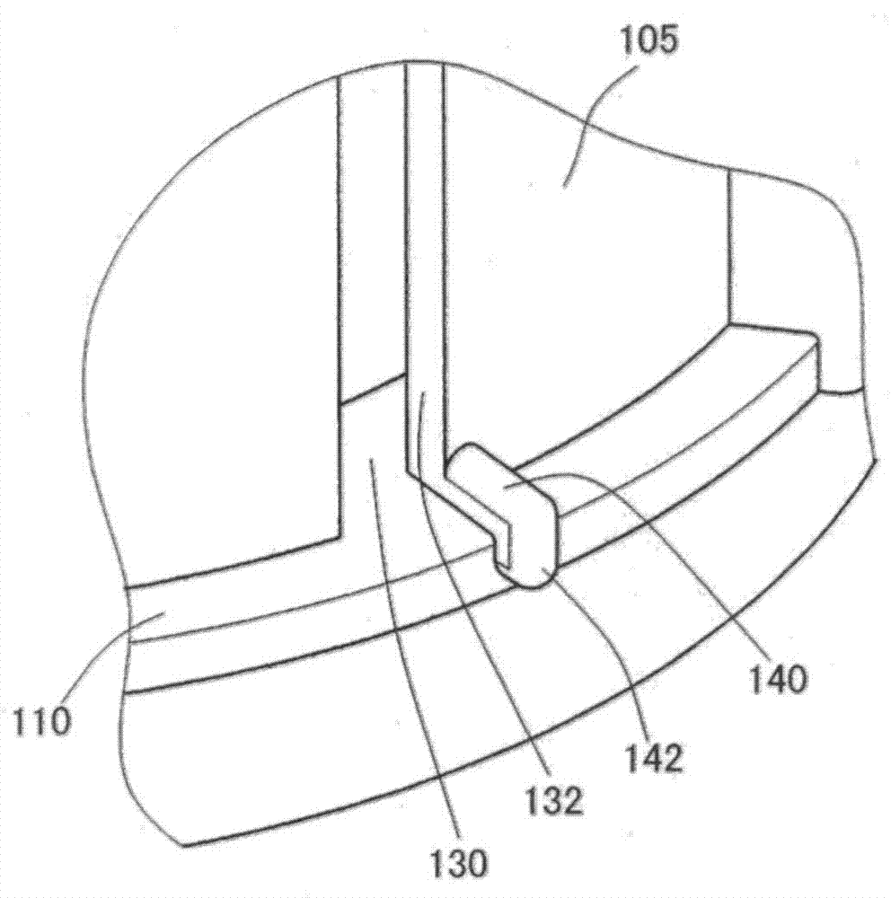
  • Figure 3
    Figure 3
Patent Text Reader

Abstract

A drain pump (1a) includes rotating blades (20) inside a pump case (10), and is driven by a motor (30). A motor lower case (100), which is mounted at the upper part of the pump case (10) and supports the motor (30), includes: an inner cylinder (120) and an outer cylinder (105). When the pump is stopped, return water from a water pumping pipe spouts out through an opening (116) of a lid (110). Residual water (W2) on the upper surface of the lid (110) is drained through inner cylinder slits (122) and drainage slits (130). At this time, the residual water (W2) is discharged to the external smoothly under the action of surface tension generated by guide parts (ribs) (140). By using the drain pump provided by the present invention, residual water of the drain pump mounted to an inner unit of an air conditioner can be effectively discharged.
Need to check novelty before this filing date? Find Prior Art

Description

technical field

[0001] The present invention relates to a drain pump installed in an indoor unit of an air conditioner. Background technique

[0002] In the indoor unit of the air conditioner, moisture in the air condenses and adheres to the heat exchanger during cooling operation, and drips into the drain pan installed below the heat exchanger. A drain pump is installed to discharge the drain accumulated in the drain pan.

[0003] refer to Figure 8 ~ Figure 11 The structure of a conventional drain pump will be described.

[0004] Such as Figure 8 , Figure 9 As shown, the drainage pump 1 has a pump casing 10 having a suction port 12 and a discharge port 14 , and a rotating vane 20 is arranged inside the pump casing 10 . In the opening of the upper part of the pump casing 10, a Figure 9 The sealing member 18 shown in (b) and (c) is attached with the motor lower case 50 via the fastening part 16 .

[0005] The lower motor case 50 has a cover 52 covering the opening o...

Examples

Embodiment Construction

[0074] refer to figure 1 as well as figure 2 The first embodiment of the drain pump of the present invention will be described in detail.

[0075] Such as figure 1 as well as figure 2 As shown, the drain pump 1 a has a pump casing 10 having a suction port 12 and a discharge port 14 , and a rotary vane 20 is arranged inside the pump casing 10 . A sealing member 114 is inserted into an opening in the upper part of the pump housing 10 , and the motor lower case 100 is attached via a fastening part 16 . The motor lower case 100 has a cover 110 covering the opening on the upper surface of the pump casing 10 , and an opening 116 is formed at the center of the cover 110 , and the cylindrical portion 22 of the rotary vane 20 penetrates the opening 116 . .

[0076] The motor 30 is supported on the upper portion of the motor lower case 100 , and the upper portion of the motor 30 is covered by the motor upper case 40 .

[0077] figure 2 (b) clearly shows that the drive shaft 32...