High-pressure injection pump

A high-pressure injection, No. 1 technology, applied in the direction of jet pumps, pumps, pump devices, etc., can solve the problems of not being able to increase the water pressure and flow rate in the outlet pipe of the high-pressure jet pump, and unable to stabilize the water flow pressure in the outlet pipe, so as to reduce energy consumption , Increase water speed and water pressure, increase the effect of water speed

Active Publication Date: 2019-06-21
TONGLING ZHAOLIN IND & TRADE CO LTD
View PDF7 Cites 4 Cited by
  • Summary
  • Abstract
  • Description
  • Claims
  • Application Information

AI Technical Summary

Problems solved by technology

[0004] Although the flow rate of the jet pump in this technical solution is small and the head is high, this solution can neither increase the pressure and flow rate of the water flow in the outlet pipe of the high-pressure jet pump, nor stabilize the pressure of the water flow in the outlet pipe, so this technical solution still has many defects.

Method used


Image

  • High-pressure injection pump
  • High-pressure injection pump
  • High-pressure injection pump

Examples


Embodiment Construction

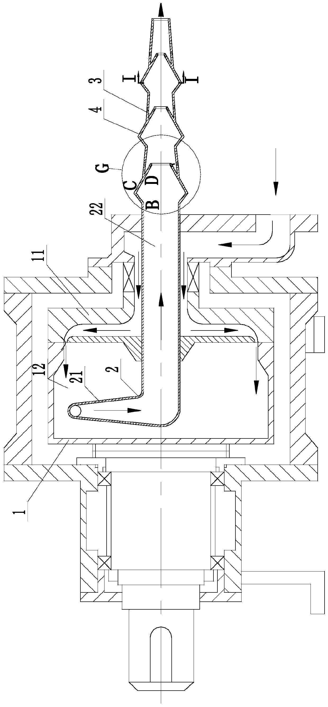
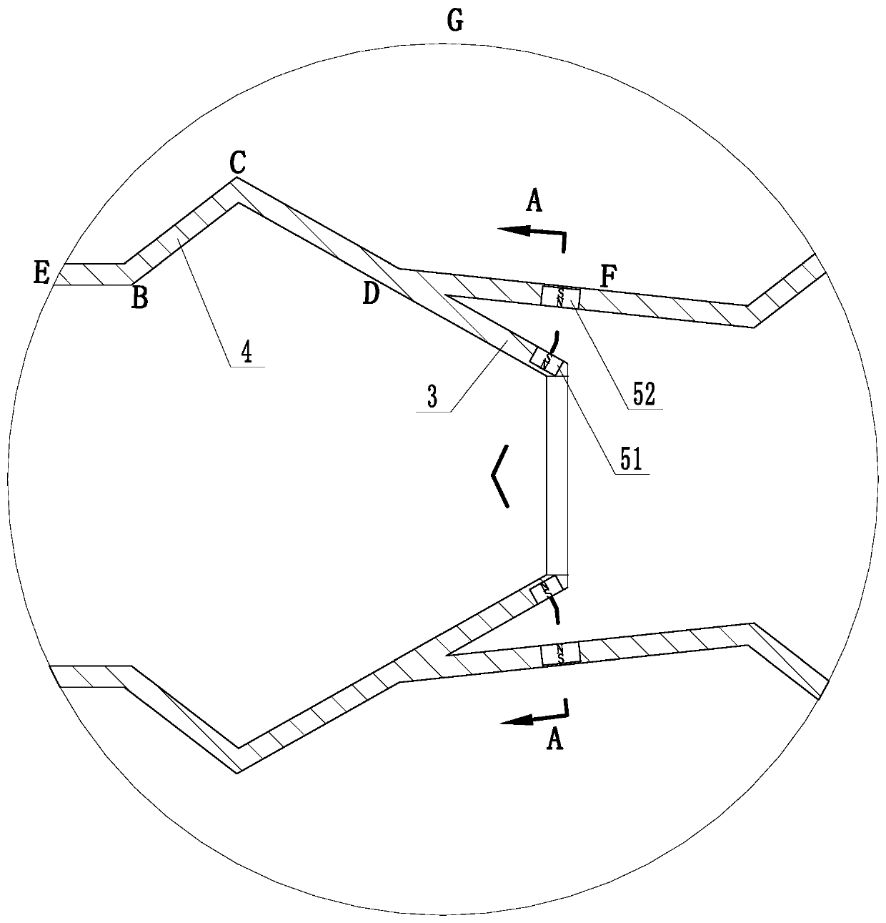
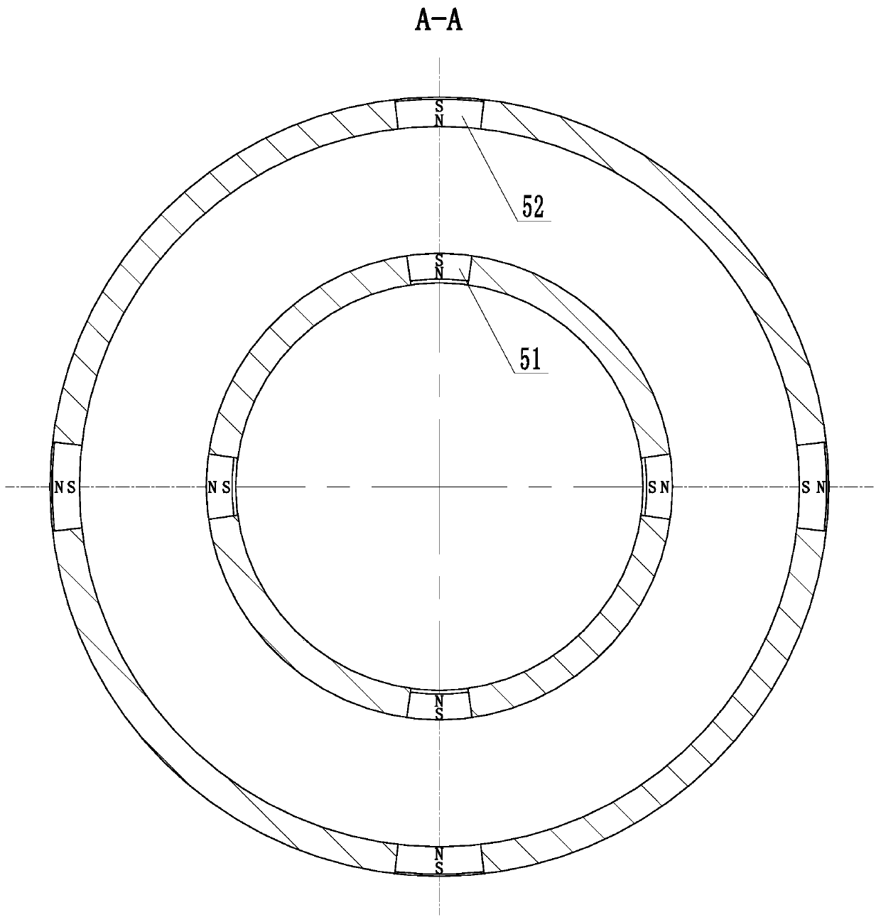
[0022] use Figure 1 to Figure 5 A high-pressure injection pump of the present invention will be described as follows.

[0023] Such as Figure 1 to Figure 5 As shown, a high-pressure jet pump according to the present invention includes a rotor body 1 and a manifold 2. The rotor body 1 includes an impeller 11 and a rotor chamber 12. The manifold 2 includes a diffuser section 21 and an outlet pipe. 22; the impeller 11 and the outlet of the impeller are arranged in the rotor chamber 12; the diffuser section 21 of the collector 2 is also arranged in the rotor chamber 12, and the outlet pipe 22 of the collector 2 is connected to the outside; its characteristics In that: the shape of the outer surface of the diffuser section 21 of the collector 2 is streamlined; the diffuser section 21 of the collector 2 is evenly distributed in an array along the circumference of the outlet pipe 22 of the collector 2, and the collector The number of diffusion sections 21 in 2 is at least three; ...


PUM


Abstract

The invention belongs to the technical field of water pumps, and particularly relates to a high-pressure injection pump. The high-pressure injection pump includes a rotor body, a collecting main, wherein the rotor body includes impellers and a rotor cavity, and the collecting main includes diffusion sections and an outlet pipe; the outer surfaces of the diffusion sections of the collecting main are in streamline shapes; and the diffusion sections of the collecting main are evenly distributed in an array mode in the circumferential direction of the outlet pipe, the number of the diffusion sections of the collecting main is at least 3, the outlet pipe of the collecting main is made of elastic materials, and the inner diameters of the cross sections of the outlet pipe are gradually decreasedfrom the left to the right. According to the high-pressure injection pump, the number of the diffusion sections of the collecting main is at least 3, thus water amount flowing into inner cavities of the diffusion sections is increased, rate of flow of water flowing into the outlet pipe and pressure of the water flowing into the outlet pipe are increased, the pressure and the rate of flow of the water flowing out of the outlet pipe are increased, the inner diameters of the cross sections of the outlet pipe are gradually decreased from the left to the right, thus when water flow passes the outlet pipe from the left to the right, water pressure is gradually increased, and thus the pressure of the water flowing out of the outlet pipe is increased.

Description

technical field [0001] The invention belongs to the technical field of water pumps, in particular to a high-pressure jet pump. Background technique [0002] In petrochemical, oil and gas field development projects, water injection and drainage, papermaking, mining, powder metallurgy and other industries, pumps with small flow and high lift are required. Usually people tend to use centrifugal pumps instead. Although the centrifugal pump has a small flow rate, its head is low. In order to increase the head, people use multistage centrifugal pumps. Multistage centrifugal pumps not only have high cost, but also have many friction points, high failure rate and low efficiency. The jet pump uses the transformation of fluid flow energy to achieve the purpose of transportation. It can transport liquid and gas. According to the working fluid used, it is generally divided into steam jet pump and water jet pump. The jet pump is simple in structure and easy to use. The jet pump is a ...

Claims


Application Information

Patent Timeline
Patent Type & Authority Applications(China)
IPC IPC(8): F04B23/14F04F5/12F04F5/44
Inventor 李河徐亚琴董军辉
Owner TONGLING ZHAOLIN IND & TRADE CO LTD
Why Eureka
Try Eureka