Air film hole channel structure based on Tesla valve and application of air film hole channel structure to front edge of turbine blade

A channel structure, air film hole technology, applied in the direction of the stator, engine components, machines/engines, etc., can solve the problem that the front edge of the vane and the end wall near the pressure surface cannot be effectively cooled, so as to prevent the high-temperature gas from flowing backward and cooling Increased flow rate and excellent cooling efficiency

Active Publication Date: 2021-08-10
NORTHWESTERN POLYTECHNICAL UNIV +1
View PDF16 Cites 4 Cited by
  • Summary
  • Abstract
  • Description
  • Claims
  • Application Information

AI Technical Summary

Problems solved by technology

[0008] In order to avoid the deficiencies of the prior art, aiming at the problem that the end wall of the gas turbine vane passage bears extremely high heat load and the conventional method cannot effectively cool the front edge of the vane and the end wall near the pressure surface side, the purpose of the present invention It is to propose a film hole channel structure based on the Tesla valve, which can improve the cooling efficiency of the end wall of the vane channel; according to the principle of the Tesla valve, the cooling jet loss from the film hole at the leading edge of the vane is reduced, The distribution is more uniform, which significantly improves the cooling efficiency of the front edge of the vane and the end wall near the pressure side to prolong the service life of the end wall near the vane, and also ensures that the end wall near the front edge of the vane can work safely and effectively

Method used


Image

  • Air film hole channel structure based on Tesla valve and application of air film hole channel structure to front edge of turbine blade
  • Air film hole channel structure based on Tesla valve and application of air film hole channel structure to front edge of turbine blade
  • Air film hole channel structure based on Tesla valve and application of air film hole channel structure to front edge of turbine blade

Examples


specific Embodiment

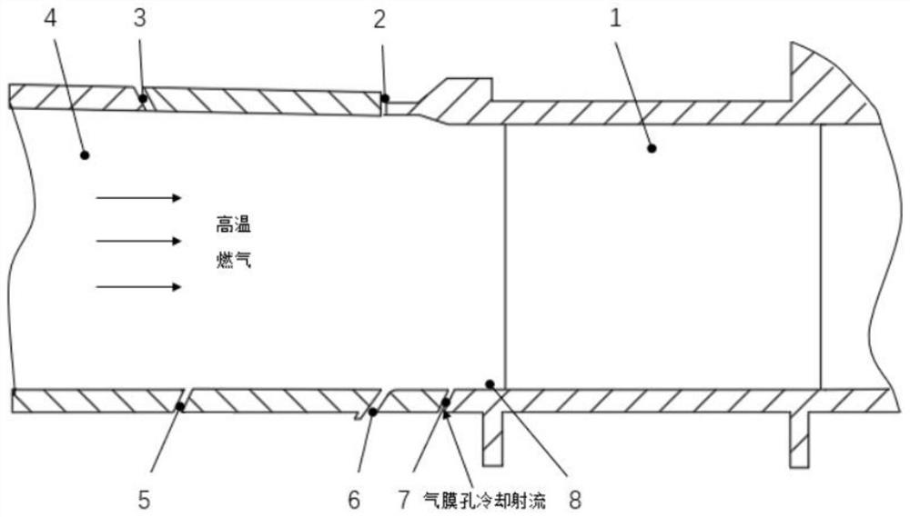
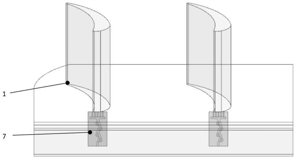
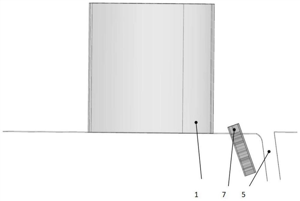
[0045] see Figure 2 to Figure 4 , the gas film hole channel structure based on the Tesla valve in this embodiment corresponds to the position of the leading edge point of the turbine vane, and the gas film hole channel structure of the Tesla valve includes five outlet gas film holes arranged side by side, The film cooling jet introduced from the compressor flows out through the channel of the Tesla valve and the five outlet film holes connected to it. Due to the one-way conduction performance of the Tesla valve, most of the cooling jet can reach the front of the vane The edge end wall greatly reduces the backflow of high temperature airflow.

[0046] see Figure 5 to Figure 8 , the film cooling jet enters the Tesla valve channel from the Tesla valve channel inlet 9 of the lower part of the Tesla valve film hole structure, and flows out through five outlet film holes 10 . In this embodiment, the Tesla valve has a four-stage structure, consisting of four Tesla valve internal ...


PUM


Abstract

The invention discloses an air film hole channel structure based on a Tesla valve and application of the air film hole channel structure to the front edge of a turbine blade, and belongs to the field of gas turbines. The air film hole channel structure comprises a Tesla valve channel and outlet air film holes, wherein the Tesla valve channel is of a Tesla valve structure, cooling airflow flows from an inlet to an outlet of the Tesla valve channel in a one-way mode, the multiple outlet air film holes are located at the outlet of the Tesla valve channel and used for introducing cooling gas into the wall face to be cooled, and the axial direction of the outlet gas film holes is parallel to the axial direction of the outlet of the Tesla valve channel. According to the air film hole channel structure, the Tesla valve channel is introduced to a film hole in the front edge of the end wall of a stationary blade, and the geometric dimension of the Tesla valve channel is matched with that of the film hole; and due to the introduction of the Tesla valve channel, not only is the backflow of high-temperature airflow obviously weakened, but also the end wall near the stagnation point of the front edge of the stationary blade and the suction surface of the stationary blade can be cooled more sufficiently and uniformly, so that the cooling efficiency is improved.

Description

technical field [0001] The invention belongs to the field of gas turbines, and in particular relates to a gas film hole channel structure based on a Tesla valve and its application on the leading edge of a turbine blade. Background technique [0002] As a device for converting and utilizing energy, gas turbines are widely used in aviation, ships, electric power and other fields. The gas turbine is in the harsh working environment of high temperature and high pressure. At the same time, due to environmental problems and energy requirements, the power and thermal efficiency of the gas turbine need to be continuously improved. These put forward stricter requirements for the design of the gas turbine. In order to cope with environmental pollution and energy demand, during the process of gas turbine R&D and design, the thermal efficiency of the gas turbine is improved by continuously increasing the inlet gas temperature. At present, the inlet temperature of the high-pressure turb...

Claims


Application Information

Patent Timeline
Patent Type & Authority Applications(China)
IPC IPC(8): F01D9/02F01D25/12
CPCF01D9/02F01D25/12
Inventor 杜昆赵江彬黄维娜吴跃腾刘存良陈磊陈麒好孟宪龙黄盛
Owner NORTHWESTERN POLYTECHNICAL UNIV
Why Eureka
Try Eureka