
Method for making low clast bullet and bullet made by the method

A production method and technology of perforating bullets, which are applied in the direction of cartridge ammunition, ammunition, weapon accessories, etc., can solve problems affecting production safety, hazards, and damage to wellhead facilities, so as to improve perforating effects, reduce costs, and improve safety Effect

Inactive Publication Date: 2006-02-22
CHUANNAN MACHINERY PLANT CHINA ASTRONAUTIC SCI &TECH GROUP CORP
View PDF0 Cites 2 Cited by
  • Summary
  • Abstract
  • Description
  • Claims
  • Application Information

AI Technical Summary

Problems solved by technology

In the perforation operation of oil wells with large aperture and high hole density, due to the low melting point of the steel bullet casing, it is difficult to vaporize, resulting in larger flaky debris (greater than 8mm) formed by the steel bullet casing after the perforating bullet explodes. Big hazard: First, after the perforation process is completed, when the perforation string is raised for sand control completion operations, large perforating bullet debris will jam the sand control string; second, when directly mining after perforation, Perforating bullet fragments rushing out of the wellhead will cause damage to wellhead facilities such as Christmas trees and affect safe production
At the same time, the structural size of each component of the perforating charge is not perfect, which also leads to the unsatisfactory perforating effect of the perforating charge

Method used


Image

  • Method for making low clast bullet and bullet made by the method
  • Method for making low clast bullet and bullet made by the method
  • Method for making low clast bullet and bullet made by the method

Examples


Embodiment Construction

[0017] The present invention is described in detail below in conjunction with accompanying drawing and embodiment:

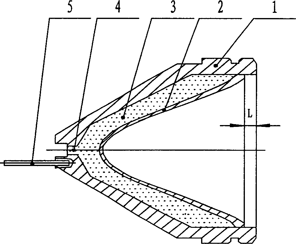
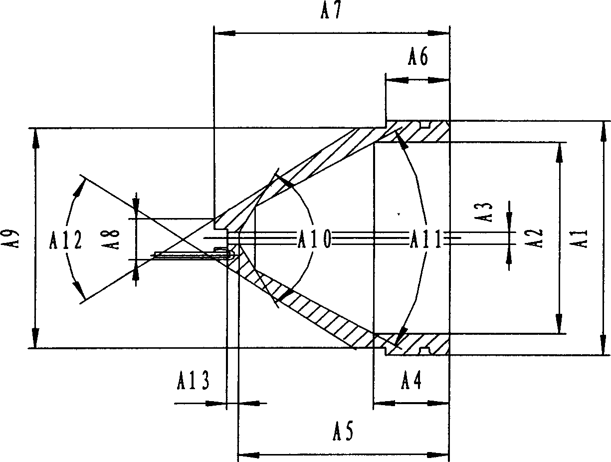
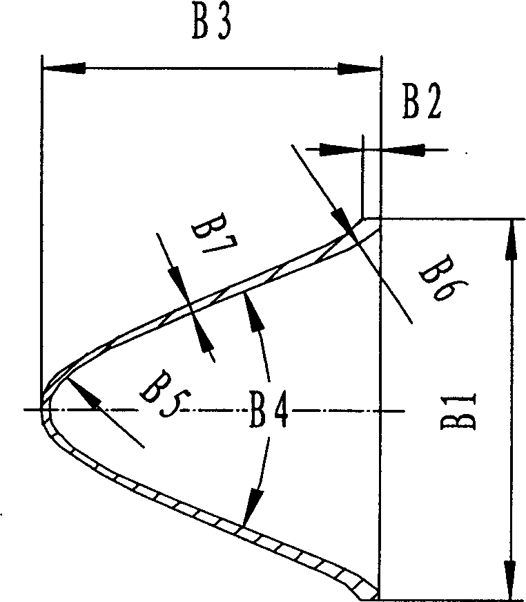
[0018] refer to Figure 1-Figure 3 , the low debris perforating charge is composed of a shell case 1, a booster charge 4, a main charge 3, and a drug-shaped cover 2. The front part of the shell case 1 is flat-headed and conical. The rear part is cylindrical, the front outer surface of the cartridge case 1 and the front part of the inner cavity are conical, the conical drug-shaped cover 2 is arranged in the cartridge case 1, and a booster charge 4 is arranged between the drug-shaped cover 2 and the inner wall of the cartridge case 1 And the main charge 3, the cartridge case 1 is made of zinc-aluminum alloy die-casting or ductile iron. For the zinc-aluminum alloy, the weight parts of zinc and aluminum in the total weight are 75-98 zinc and 25-2 aluminum, specific examples are: 75 zinc, 25 aluminum; 98 zinc, 2 aluminum; 85 zinc, 15 aluminum. For the ductile iron ...


PUM

PropertyMeasurementUnit
lengthaaaaaaaaaa
diameteraaaaaaaaaa
lengthaaaaaaaaaa

Abstract

This invention relates to a method for manufacturing the small-chip projectile in oil well operation, characterized in that the shell case is die cast with aluminum zinc alloy, wherein the weight ratio is: zinc 75-98, aluminum 25-2; the weight ratio of the nodular graphite cast iron shell case is: carbon 1-5, silicon 1-3, iron 92-98. The projectile comprises shell case, booster, main charge and medical shield, wherein the front of the shell case is tack conical, and the booster is set in the front of the shell case; the rear of the shell case is cylinder shape; the medical shield is set in the shell case, and between the medical shield and the shell case inner it sets the booster and the main charge. After gun perforation, the shell case chip is small in powder or particle shape, which does not damage the sand control pipe column and the well facilities.

Description

technical field [0001] The invention relates to a method for making a low debris perforating bullet used in oil well perforating operations and the perforating bullet. Background technique [0002] In the petroleum industry, oil well perforation operation is an important process. It is to install the high-energy perforating bullet in the perforating gun, and detonate it after it reaches the target layer in the well. After detonation, the high-energy perforation After the bullet penetrates the perforating gun, it further shoots through the casing and cement layer of the well wall, so that the formation and the oil well are connected, so that the oil and gas in the formation can flow into the oil well smoothly. Usually the perforating charge is composed of a steel shell, a booster, a main charge, and a drug cover. The front part and the inner cavity of the shell are in the shape of a cone. A booster charge and a main charge are provided. After the main charge is detonated, t...

Claims


Application Information

Patent Timeline
Patent Type & Authority Applications(China)
IPC IPC(8): F42B5/192F42B5/188
CPCF42B1/02F42B1/036
Inventor 冯启先徐德昭陈宇重成兴
Owner CHUANNAN MACHINERY PLANT CHINA ASTRONAUTIC SCI &TECH GROUP CORP
Learn More