Track breaking monitoring system of high-speed railway

A high-speed railway and monitoring system technology, which is applied in the direction of railway vehicle shape measuring devices, railway car body parts, railway auxiliary equipment, etc., can solve the problems of poor detection accuracy, shallow detection depth, and no solution proposed, and achieve good stability , Strong anti-interference ability

CN104554343AActive Publication Date: 2015-04-29北京运吉强科技有限公司
4 Cites 7 Cited by

Patent Information

Authority / Receiving Office
CN · China
Patent Type
Applications(China)
Current Assignee / Owner
Publication Date
2015-04-29

Smart Images

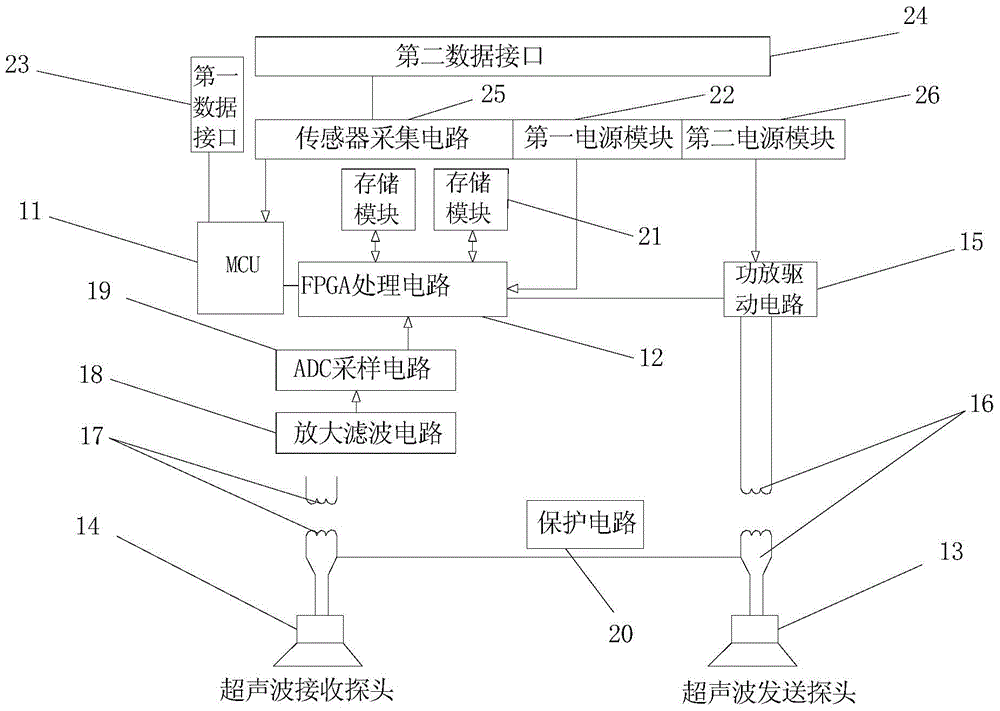
  • Figure 1
    Figure 1
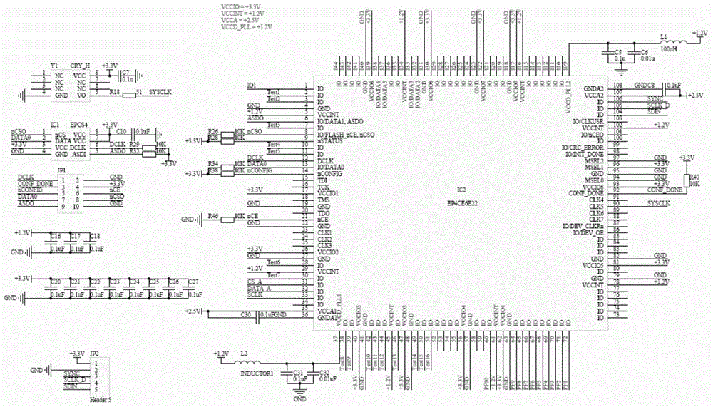
  • Figure 2
    Figure 2
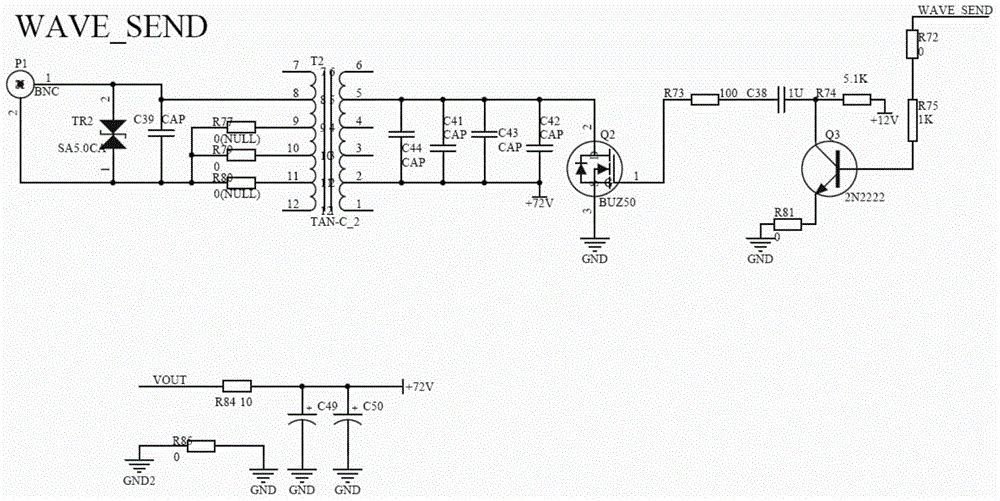
  • Figure 3
    Figure 3
Patent Text Reader

Abstract

The invention provides a track breaking monitoring system of a high-speed railway. The system comprises a MCU for generating a testing signal according to received instruction information and sending to an ultrasonic sending probe, the ultrasonic sending probe for receiving the testing signal and sending an ultrasonic signal to a high-speed railway track according to the testing signal, an ultrasonic receiving probe for receiving the ultrasonic signal from the high-speed railway track and sending the ultrasonic signal to an FPGA processing circuit, and the FPGA processing circuit for performing digital filter and FFT analysis for the ultrasonic signal as well as carrying out frequency spectrum comparison and signal correlation comparing and analyzing for the FFT analysis result so as to determine the track breaking condition of the high-speed railway. According to the track breaking monitoring system of the high-speed railway, the measures of shielding and isolating loops are carried out to increase the signal conversion quality, and the influence of an electromagnetic environment on the detection result is reduced; in addition, the wavelet analysis algorithm is carried out for the FPGA processing circuit, and therefore, the signal receiving sensitivity is high, and the measurement distance is effectively increased.
Need to check novelty before this filing date? Find Prior Art

Description

technical field

[0001] The invention relates to the field of railway broken track monitoring, in particular to a high-speed railway broken track monitoring system. Background technique

[0002] High-speed railway (referred to as high-speed railway) refers to the transformation of the original line (linearization, standardized gauge), so that the maximum operating speed can reach no less than 200 kilometers per hour, or specially build a new "high-speed new line", so that the operating speed can reach 200 kilometers per hour. A rail system with at least 250 kilometers per hour. For high-speed railways, in addition to reaching a certain speed standard in train operation, the vehicles, rails, and operations all need to be upgraded.

[0003] The emergence of high-speed railways has undoubtedly brought great convenience to people's lives, but on high-speed railways, trains have been running at high speeds, so it is easier to cause rail breakage. Therefore, the relevant technolo...

Examples

specific Embodiment

[0058] combine figure 1 The schematic diagram of the structure of the high-speed railway track breaking monitoring system provided by the embodiment of the present invention and Figure 2-Figure 16 The specific circuit diagram in the broken track monitoring system of the high-speed railway shown is described in detail to the broken track monitoring system of the high-speed railway track provided by the present invention, and specific embodiments are as follows:

[0059] The invention provides a high-speed railway broken track monitoring system, such as figure 1 As shown, it includes: micro control unit MCU11 (Micro Controller Unit, Chinese name micro control unit), FPGA (Field Programmable Gate Array, Field Programmable Gate Array) processing circuit, ultrasonic sending probe 13 and ultrasonic receiving probe 14;

[0060] MCU11 is used to generate test signal according to the instruction information received, and test signal is sent to ultrasonic sending probe 13; The ultras...