
Method for Measuring Filtration Coefficient of Supercritical Carbon Dioxide Fracturing Fluid

A carbon dioxide, supercritical technology that can be used in measurement devices, surface/boundary effects, suspension and porous material analysis, etc., to solve problems such as narrowing of cracks, sand plugging, and unsatisfactory stimulation effects.

Inactive Publication Date: 2017-08-11
CHINA UNIV OF PETROLEUM (EAST CHINA)
View PDF7 Cites 0 Cited by
  • Summary
  • Abstract
  • Description
  • Claims
  • Application Information

AI Technical Summary

Problems solved by technology

Excessive fracturing fluid fluid loss will also lead to gradual accumulation of proppant, increasing the proppant content in fractures, prone to sand plugging, and wellbore collapse
After fracturing, under a certain fluid loss rate, the formed fractures can be closed in time, but when the fluid loss rate is too slow, the proppant will quickly deposit in the fracture, which will affect the uniform distribution of proppant in the fracture, and cannot Supporting the entire height of the fracture, the width of the fracture becomes narrower, and the stimulation effect is not ideal
Therefore, the key parameter for optimal design of fracturing hydraulic parameters using supercritical carbon dioxide fracturing is to determine the fluid loss coefficient of supercritical carbon dioxide fracturing fluid; at present, there are no reports on the fluid loss performance of supercritical carbon dioxide fracturing fluid in China

Method used


Image

  • Method for Measuring Filtration Coefficient of Supercritical Carbon Dioxide Fracturing Fluid
  • Method for Measuring Filtration Coefficient of Supercritical Carbon Dioxide Fracturing Fluid
  • Method for Measuring Filtration Coefficient of Supercritical Carbon Dioxide Fracturing Fluid

Examples


Embodiment Construction

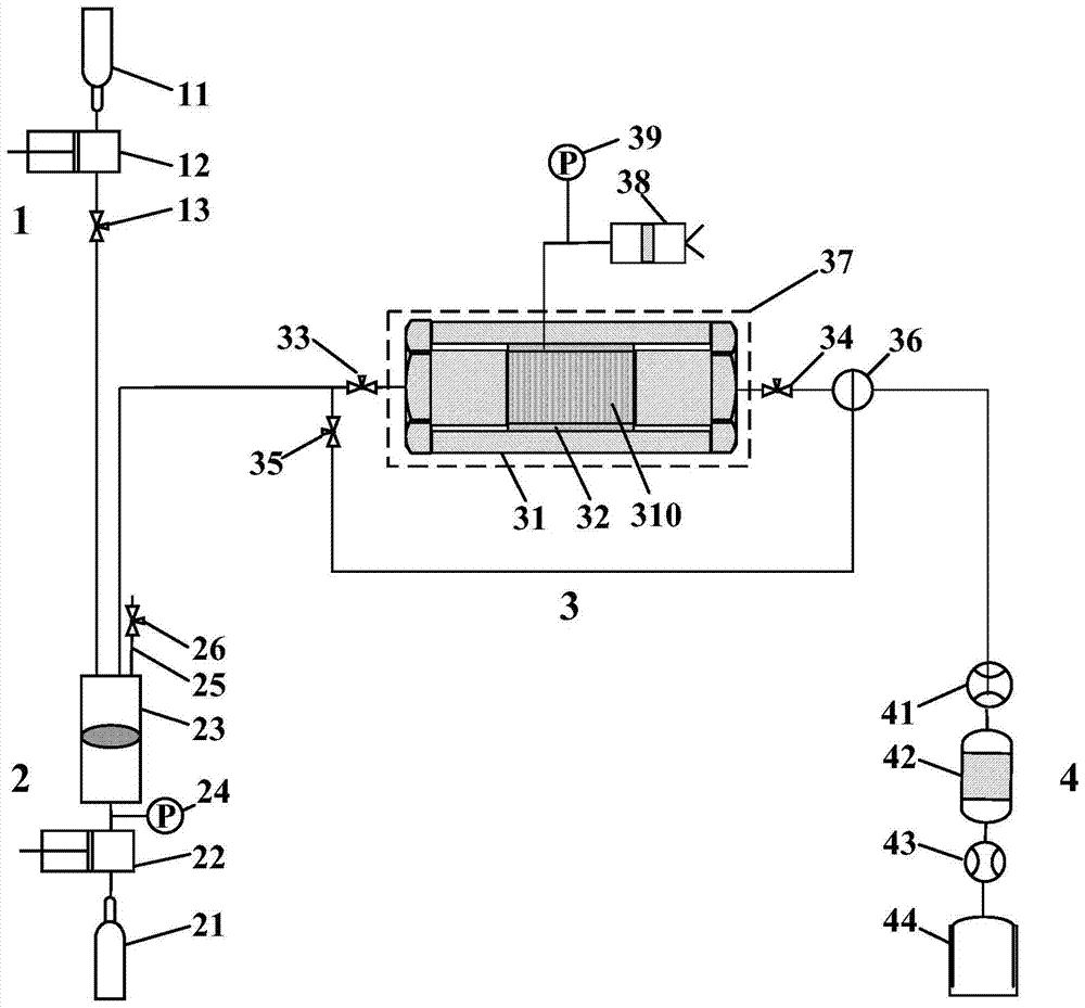
[0023] Such as figure 1 As shown, the device for measuring the fluid loss coefficient of supercritical carbon dioxide fracturing fluid includes: gas injection system 1, pressure control system 2, experimental model system 3 and measurement system 4; gas injection system 1 injects methane or carbon dioxide into the experimental model system 3 , the pressure control system 2 provides pressure for the experimental model system 3 and the gas injection system 1, the experimental model system 3 provides a high temperature and high pressure formation environment for the experiment, and the measurement system 4 measures the volume of different gases flowing out during the experiment.

[0024] The gas injection system 1 includes: a gas storage tank 11, a gas booster pump 12, a gas output screw valve 13, the gas storage tank 11, a gas booster pump 12, and a gas output screw valve 13 are connected in sequence through pipelines, and the gas storage tank 11 is a standard stainless steel ga...


PUM


Abstract

The invention belongs to the technical field of unconventional oil and gas stimulation, and in particular relates to a method for measuring the fluid loss coefficient of supercritical carbon dioxide fracturing fluid, which is used for determining the fluid loss coefficient of supercritical carbon dioxide fracturing fluid. The method for measuring the fluid loss coefficient of supercritical carbon dioxide fracturing fluid, the steps are as follows: (1), place the rock core, (2), discharge the gas in the upper cavity of the intermediate container, and fill the upper cavity of the intermediate container with methane, (3), Apply pressure to the lower cavity of the intermediate vessel, (4), inject methane into the rock core, (5), empty the methane in the upper cavity of the intermediate vessel and inject carbon dioxide, (6), apply confining pressure, (7), apply back pressure, ( 8), injecting carbon dioxide into the rock core, (9), calculating the filtration rate and filtration coefficient. The temperature and pressure of the method of the invention can be adjusted to meet the high-temperature and high-pressure environment requirements in which the carbon dioxide reaches a supercritical state, and can truly study the filtration law of the supercritical carbon dioxide fracturing fluid under different temperature and pressure conditions.

Description

technical field [0001] The invention belongs to the technical field of unconventional oil and gas stimulation, and in particular relates to a device and method for measuring the fluid loss coefficient of supercritical carbon dioxide fracturing fluid, which is used to study the fluid loss of supercritical carbon dioxide fracturing fluid in unconventional oil and gas fracturing stimulation engineering To determine the fluid loss coefficient of supercritical carbon dioxide fracturing fluid. Background technique [0002] Supercritical carbon dioxide (SC-CO 2 ) fracturing is a new type of unconventional oil and gas reservoir stimulation technology. It has a series of advantages that cannot be compared with conventional hydraulic fracturing technology. means. [0003] Supercritical carbon dioxide fracturing fluid has many characteristics such as less formation damage, viscosity reduction, anti-swelling, resistance reduction, and drainage aid. When the injection volume is constan...

Claims


Application Information

Patent Timeline
Patent Type & Authority Patents(China)
IPC IPC(8): G01N15/08G01N13/04
Inventor 李庆建李庆超孙文超张彦龙杜庆杰
Owner CHINA UNIV OF PETROLEUM (EAST CHINA)
Learn More