Light guide plate and display module

A display module and light guide plate technology, which is applied in the field of backlight display, can solve problems such as difficult breakthroughs and insignificant light guide uniformity, and achieve the effect of improving backlight uniformity and backlight effect

Inactive Publication Date: 2015-04-29
TCL CHINA STAR OPTOELECTRONICS TECH CO LTD
View PDF7 Cites 1 Cited by
  • Summary
  • Abstract
  • Description
  • Claims
  • Application Information

AI Technical Summary

Problems solved by technology

However, this method does not have a significant effect on improving the uniformity of light guide, and it is difficult to achieve a big breakthrough

Method used


Image

  • Light guide plate and display module
  • Light guide plate and display module
  • Light guide plate and display module

Examples


Embodiment 1

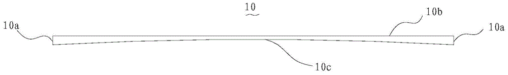
[0024] refer to Figure 1~2 The light guide plate 10 of this embodiment includes light incident surfaces 10a on both sides, a light exit surface 10b on the upper surface, and a scattering surface 10c with scattering dots on the lower surface, and the scattering surface 10c is recessed toward the direction of the light exit surface 10b.

[0025] Since the scattering surface 10c is recessed toward the light-emitting surface 10b, the light entering the light-incident surface 10a on both sides can enter the scattering surface 10c through a very short optical path, and then diverge toward the surroundings through the scattering surface 10c, and finally exit the light-emitting surface 10b has more even light.

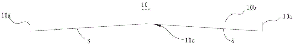
[0026] Specifically, the scattering surface 10c is an arc surface (such as figure 1 shown). Alternatively, the scattering surface 10c is composed of a slope S inclined from the lower ends of the light incident surface 10a on both sides toward the light exit surface 10b (suc...

Embodiment 2

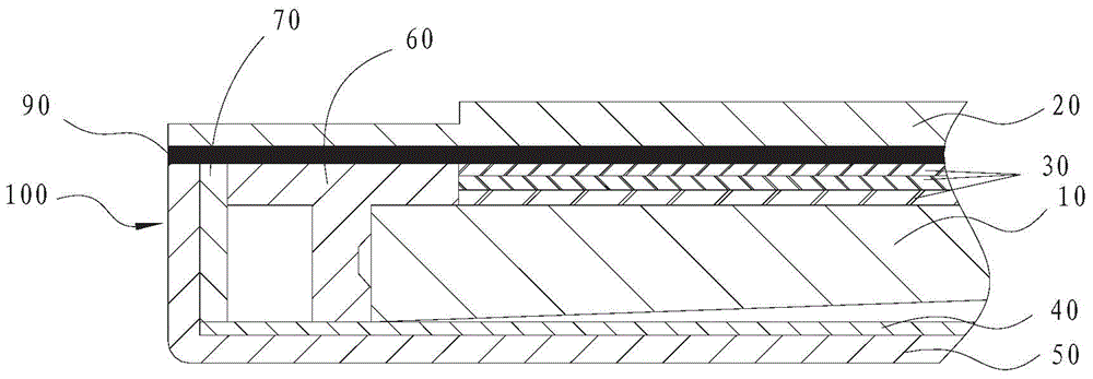
[0030] Such as Figure 4 As shown, the difference from Embodiment 1 is that the scattering surface 10c of this embodiment is coated with a reflective material, and the reflective material layer 10s is the reflective layer 40 of the backlight unit 100 to reflect the light emitted from the LED components 60 on both sides. The light entering the scattering surface 10c.

Embodiment 3

[0032] Such as Figure 5 As shown, the difference from Embodiment 1 is that the reflective layer 40 of this embodiment is a layer of reflective sheet provided separately, and the reflective sheet is closely attached to the scattering surface 10c.


PUM


Abstract

The invention discloses a light guide plate which comprises incident faces on the two sides, an emergent face on the upper surface and a scattering face provided with scattering net points and arranged on the lower surface. The scattering face is recessed towards the emergent face. The invention further provides a display module which comprises a display panel and a backlight unit. The backlight unit comprises the light guide plate and LED assemblies arranged on the two sides of the light guide plate. By the adoption of the two-side incident structure, and meanwhile, the scattering face at the bottom is recessed towards the emergent face, backlight evenness of the light guide plate is well improved, and the backlight effect can be improved.

Description

technical field [0001] The invention relates to the technical field of backlight display, in particular to a light guide plate and a display module. Background technique [0002] With the development of consumer electronics technology, the improvement of the uniformity of the backlight of the display device is of great significance for improving the competitiveness of the product. The existing light guide plate is usually designed as a rectangular plate structure, and at the same time, the dots that are conducive to astigmatism are designed on the bottom of the light guide plate to realize the reflection of light. However, this method does not have a significant effect on improving the uniformity of light guide, and it is difficult to achieve a major breakthrough. Contents of the invention [0003] In view of the deficiencies in the prior art, the present invention provides a light guide plate and a display module with good backlight uniformity. [0004] In order to achi...

Claims


Application Information

Patent Timeline
Patent Type & Authority Applications(China)
IPC IPC(8): G02B6/00G02B5/02F21S8/00F21V8/00F21Y101/02
CPCG02B6/0041G02B6/0055G02B5/021G02B6/0043G02B6/0046
Inventor 张彦学
Owner TCL CHINA STAR OPTOELECTRONICS TECH CO LTD
Why Eureka
Try Eureka