Multi-hole filling nozzle and components thereof
A technology of porous nozzles and components, which is applied in the field of porous filling nozzles and their components, and can solve the problem that the search for nozzles is still continuing
- Summary
- Abstract
- Description
- Claims
- Application Information
AI Technical Summary
Problems solved by technology
Method used
Image


Examples
Embodiment Construction
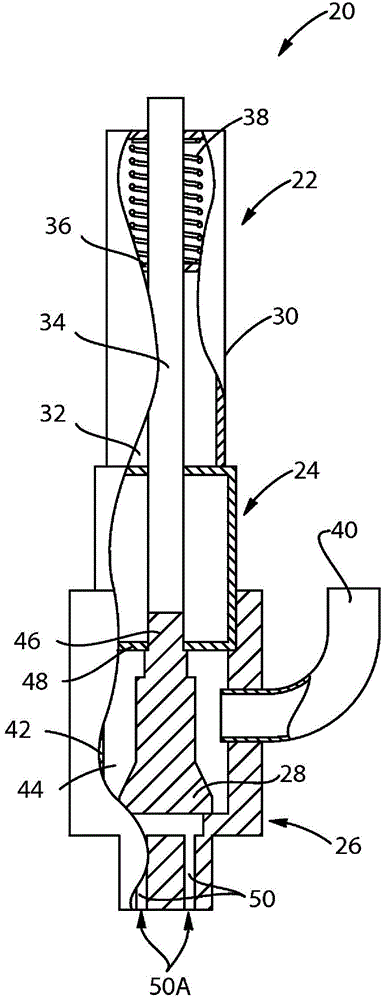
[0014] figure 1 and 2 One non-limiting example of a multi-hole nozzle assembly 20 is shown. figure 2 It is shown that the multi-hole nozzle assembly 20 may generally include a cylinder 22 , an optional connection body 24 and a nozzle body 26 . The cylinder 22 moves the plug 28 inside the nozzle body 26 to open and close the nozzle. An optional connecting body 24 connects the cylinder 22 to a nozzle body 26 . It should be understood that the nozzle body 26 or components thereof may comprise inventions that have their own rights independent and separate from the nozzle assembly 20 and that the description of the nozzle assembly is provided to show these components in context.
[0015] figure 2 It is shown that the cylinder 22 may include a housing 30 having an interior hollow space 32 therein. The cylinder 22 also includes a rod 34 , a piston 36 and a spring 38 . During operation, the cylinder 22 moves the rod 34 upwardly to open the nozzle, and downwardly to close the n...
PUM
 Abstract
Description
Claims
Application Information
 - R&D
- Intellectual Property
- Life Sciences
- Materials
- Tech Scout
- Unparalleled Data Quality
- Higher Quality Content
- 60% Fewer Hallucinations
Browse by: Latest US Patents, China's latest patents, Technical Efficacy Thesaurus, Application Domain, Technology Topic, Popular Technical Reports.
© 2025 PatSnap. All rights reserved.Legal|Privacy policy|Modern Slavery Act Transparency Statement|Sitemap|About US| Contact US: help@patsnap.com