Unconventional CO2 fracturing site operation technology

An on-site construction, CO2 technology, applied in wellbore/well components, production fluids, earth-moving drilling, etc., can solve problems such as affecting the safe and efficient production of CO

Active Publication Date: 2015-06-03
BC P INC CHINA NAT PETROLEUM CORP +1
View PDF2 Cites 24 Cited by
  • Summary
  • Abstract
  • Description
  • Claims
  • Application Information

AI Technical Summary

Problems solved by technology

Seriously affects CO 2 Safe and efficient production of fracturing

Method used


Image

  • Unconventional CO2 fracturing site operation technology

Examples


Embodiment Construction

[0036] The present invention will be further described below with reference to the accompanying drawings.

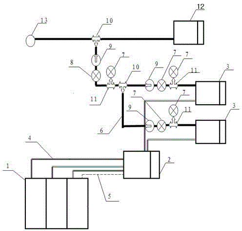
[0037] The present invention provides an unconventional CO 2 The on-site construction process of fracturing includes the following steps:

[0038] (1) Preparation of the main fracturing truck 3: cleaning the upper water chamber and the pump chamber of the large pump to prevent the thread seal of the upper water chamber from being loosely sealed, and in the gas phase CO 2 A puncture occurred while purging the line. Specifically include the following:

[0039] Clean the upper water chamber and large pump chamber of each main fracturing truck 3 one day in advance to remove sand and other debris to avoid clogging the pipeline, and at the same time dry the water and wipe it. Due to liquid CO 2 The temperature is -18°C. If there is moisture, it will freeze instantly, causing the valve head and the valve seat in the large pump to adhere and cannot be separated, or because t...


PUM


Abstract

The invention provides an unconventional CO2 fracturing site operation technology. The technology comprises the steps of (1) preparation of a fracturing truck; (2) the connection between a CO2 booster pump truck and a CO2 storage tank and a main fracturing truck; (3) the connection of high pressure lines; (4) pressure testing; (5) high pressure line sweeping; (6) circulatory pump cooling; (7) CO2 fracturing; (8) pressure release. By means of the technology, the risk of dry icing can be eliminated, the expansion explosion risk is eliminated, and the unconventional CO2 fracturing can be completed safely.

Description

technical field [0001] The present invention relates to the fracturing technology of oil and gas field, especially unconventional CO 2 On-site construction techniques for fracturing. Background technique [0002] Fracturing is the main method for formation stimulation, and in addition to conventional fracturing, there are also CO 2 Energized fracturing, CO 2 Foam fracturing, pure CO 2 Fracturing and other unconventional CO 2 Fracturing stimulation measures. Unconventional CO 2 Compared with conventional fracturing, fracturing has the following advantages: [0003] Conventional fracturing is mainly based on water-based fracturing fluid. Due to the high surface tension of the fracturing fluid, it is difficult to flow back after fracturing, or it cannot be completely reversed, which will cause great damage to the formation. while CO 2 Fracturing reduces the surface tension of the fracturing fluid, and also provides gas displacement for the flowback of the working fluid ...

Claims


Application Information

Patent Timeline
Patent Type & Authority Applications(China)
IPC IPC(8): E21B43/26
CPCE21B43/164E21B43/26
Inventor 费节高郭春峰白明伟詹勇韩旭辉邓斌奇张铁军张小平刘广春郑松柏乔晓东张庆峰高红平王美琴纪冬冬
Owner BC P INC CHINA NAT PETROLEUM CORP
Why Eureka
Try Eureka