Zipper slider

A slider and zipper technology, applied in the field of sliders for zippers, can solve the problems of complex slider assembly, heavy weight, complex slider structure, etc.

Active Publication Date: 2017-06-23
YKK CORP
View PDF2 Cites 0 Cited by
  • Summary
  • Abstract
  • Description
  • Claims
  • Application Information

AI Technical Summary

Problems solved by technology

[0009] However, the structure of the slider in Patent Document 1 is complicated, and since the second spring member (hinge spring) can be provided, the size and weight of the slider are increased, so it is difficult to achieve miniaturization or weight reduction.
In addition, the assembly work of the slider is complicated, so there is room for improvement from the viewpoint of work efficiency and manufacturing cost

Method used


Image

  • Zipper slider
  • Zipper slider
  • Zipper slider

Examples


Embodiment 1

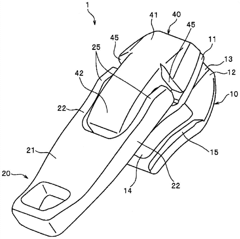
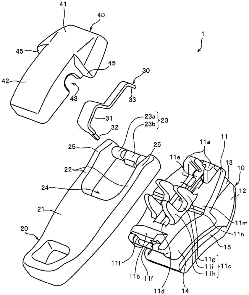
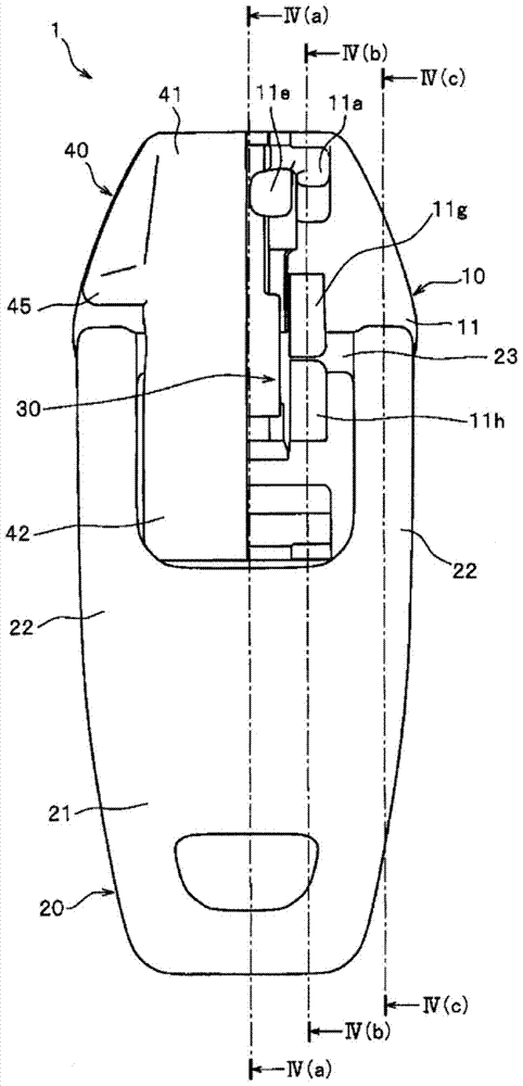
[0094] figure 1 It is a perspective view showing the slider of the first embodiment, figure 2 It is an exploded perspective view showing the disassembled state of the slider. image 3 is a top view of the slider showing a portion of the cover in perspective.

[0095] In addition, in the following description, the front-back direction of a slider means the direction (longitudinal direction of a slider) parallel to the sliding direction of a slider, and the direction which slides so that the left and right elements line up is set as Let it be the front (introduction port side direction), and let the direction which slides so that the left and right element rows may separate|separate as a rear (engagement port side direction).

[0096] In addition, the up-down direction of a slider means the height direction of a slider, and let the direction of the side where the handle is attached with respect to a slider main body be upper, and let the direction of the opposite side be low...

Embodiment 2

[0146] Figure 7 It is a perspective view showing the slider main body of the slider of the second embodiment, Figure 8 is a top view of the slider showing a portion of the cover in perspective. also, Figure 9 (a) and (b) of Figure 8 The cross-sectional view of line IX(a)-IX(a) and line IX(b)-IX(b) shown, Figure 10 (a) and (b) are cross-sectional views of the slider in the state where the handle is raised. In addition, in Figure 9 and Figure 10 In , the position of the front-back direction of the rotation center of the attachment shaft part of a handle is shown by the one-dot chain line, and illustration of a cover body is abbreviate|omitted.

[0147] In the slider 1 of the above-mentioned Example 1, the handle contact area 11m of the upper blade 11 includes a part of the main upper surface of the upper blade 11, and the non-contact area (fall-down promoting portion) includes the groove portion 11n, On the other hand, in the slider 2 of this Example 2, the handle ...

Embodiment 3

[0165] Figure 11 It is an exploded perspective view showing a disassembled state of the slider of the third embodiment, Figure 12 is a top view of the slider. Figure 13 yes Figure 12 A cross-sectional view along line XIII-XIII is shown, Figure 14 It is a cross-sectional view of the slider with the pull tab in an upright state. In addition, in Figure 13 and Figure 14 , the position in the front-rear direction of the rotation center of the attachment shaft part of the handle is shown by a dot chain line.

[0166] In the slider 3 of the present embodiment 3, the handle holders 11c and 51c arranged in the sliders 1 and 2 of the above-described embodiment 1 or 2 are not provided on the upper wing plate 61 of the present embodiment 3. , but the type of slider that holds the mounting shaft portion 73 of the pull tab 70 between the upper blade 61 of the slider body 60 and the cover 90 . Hereinafter, the slider 3 of this Example 3 is demonstrated concretely.

[0167] The...


PUM


Abstract

The invention relates to a slider for a slide fastener. The upper wing plate (11, 51, 61) of the slider (1, 2, 3) of the present invention is provided with a handle contact area (11m, 61m), and a non-contact area where the handle (20, 70) in the standing state does not come into contact is arranged on the meshing port side rather than the handle contact area (11m, 61m). This non-contact area is formed so that the position of the slider height direction may be lower than the handle contact area (11m, 61m). Thereby, the fall of the handle (20, 70) caused by the urging force of the stop pawl (30, 80) can be promoted, and the stop mechanism can be automatically and stably actuated.

Description

technical field [0001] The present invention relates to a slider for a slide fastener, in particular to a slider that can automatically fall down toward the engaging opening side of the slider main body when the slider is not slid and can maintain the down state of the slider The zipper has a slider. Background technique [0002] Conventionally, slide fasteners are attached to openings of articles such as clothes or bags, and the opening can be opened and closed by aligning or separating left and right elements by sliding a slider attached to the slide fastener along the element row. A slider for a zipper generally includes: a slider body; and a pull piece, which can be held in a rotatable manner relative to the slider body; The roughly Y-shaped sprocket guide way. [0003] Among the sliders for slide fasteners of this type, there is known one that includes a stop mechanism that makes the stop claw protrude to the element of the slider body when the slider is stopped at an...

Claims


Application Information

Patent Timeline
Patent Type & Authority Patents(China)
IPC IPC(8): A44B19/30
CPCA44B19/303
Inventor 宫崎阳平滨田嘉一槻庆一
Owner YKK CORP
Why Eureka
Try Eureka