Slider for slide fastener
A technology for sliders and zippers, which is applied in the field of zipper sliders, and can solve problems such as heavy weight, complicated slider assembly operations, and complex slider structures.
- Summary
- Abstract
- Description
- Claims
- Application Information
AI Technical Summary
Problems solved by technology
Method used
Image
Examples
Embodiment 1
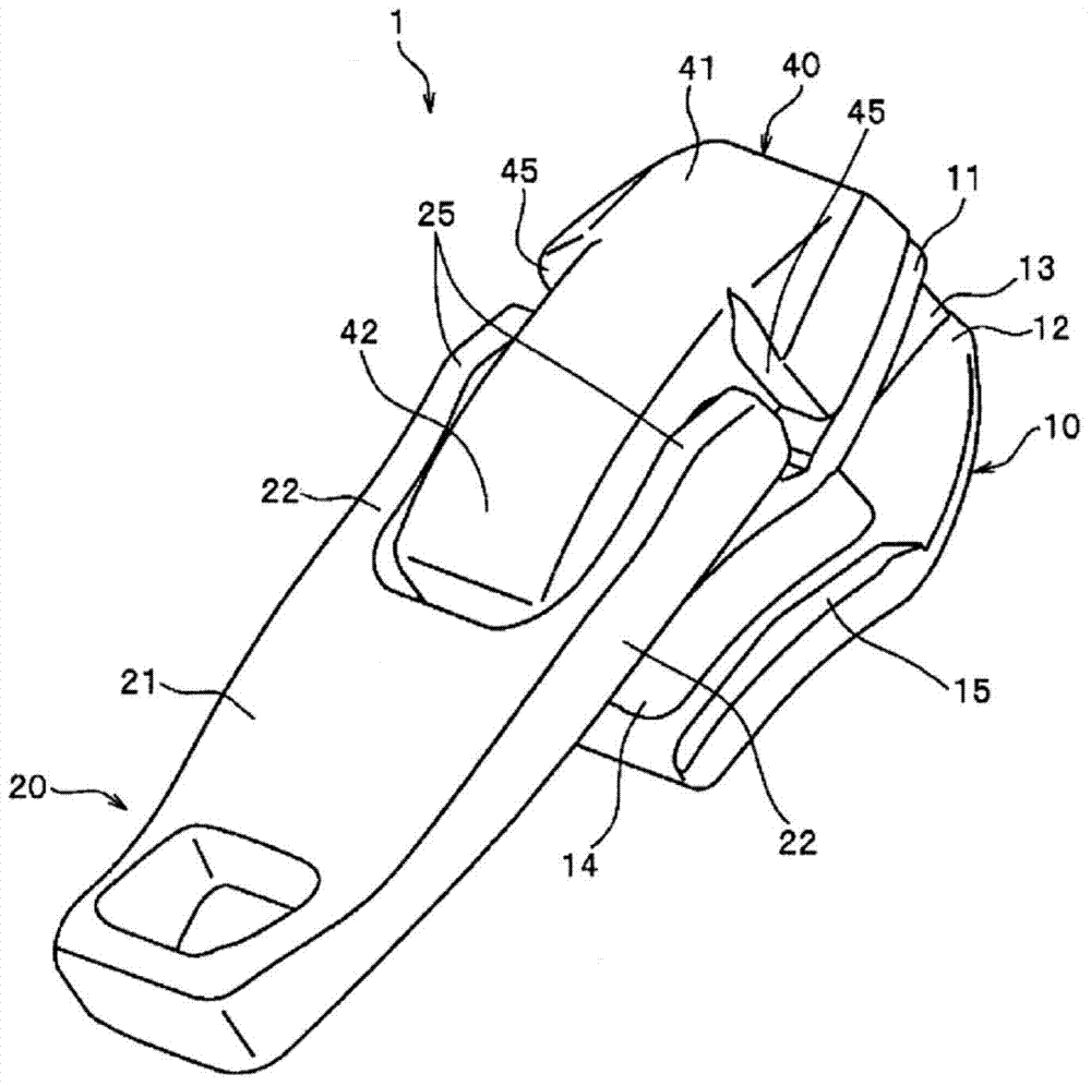
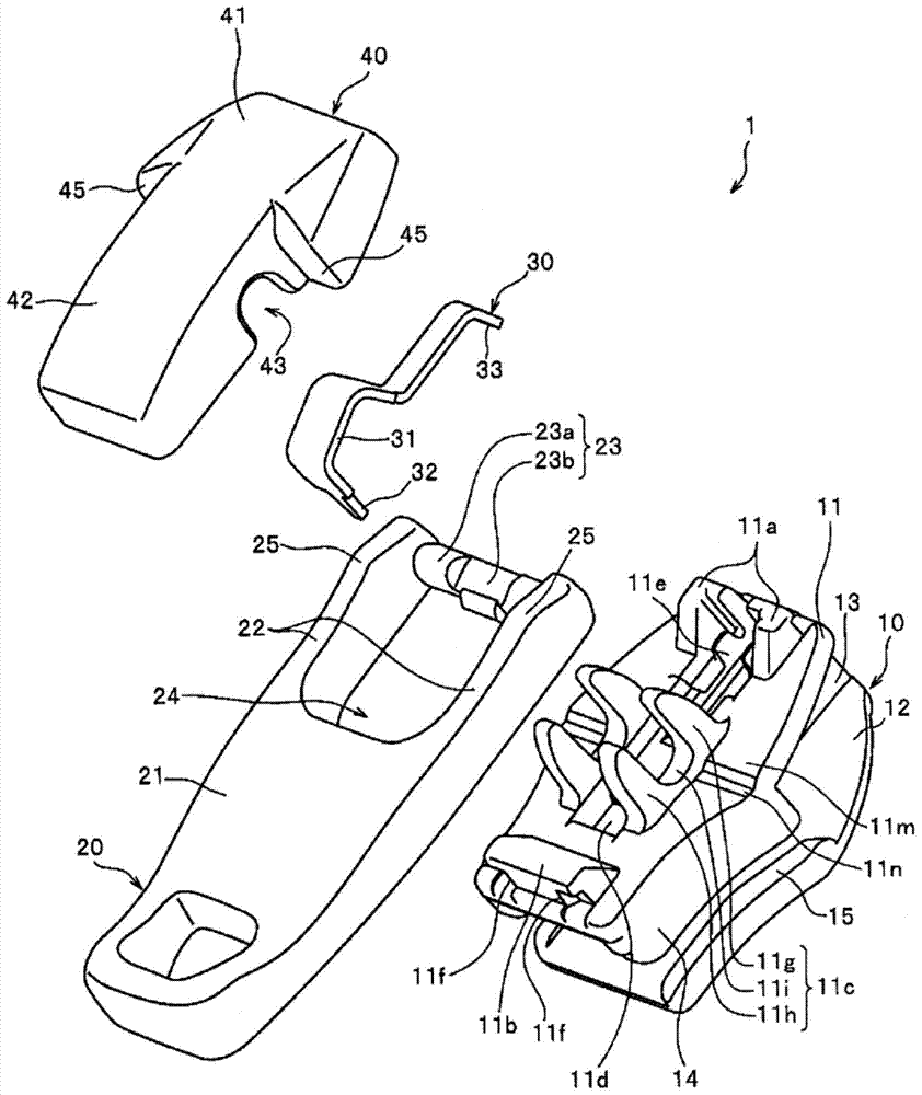
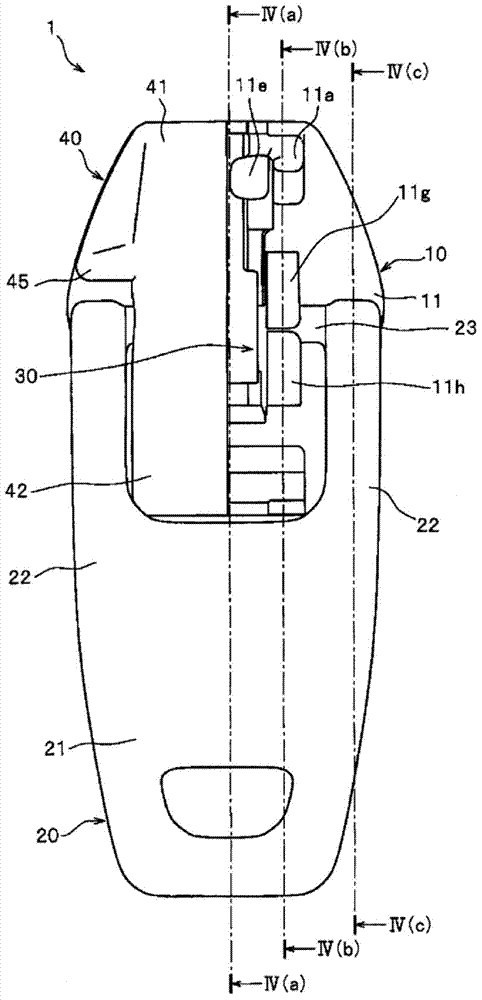
[0094] figure 1 It is a perspective view which shows the slider of this Example 1, figure 2 It is an exploded perspective view showing the disassembled state of the slider. image 3 is a top view of the slider showing a portion of the cover in perspective.
[0095] In addition, in the following description, the front-back direction of a slider means the direction (longitudinal direction of a slider) parallel to the sliding direction of a slider, and the direction which slides so that the left and right elements line up is set as Let it be the front (introduction port side direction), and let the direction which slides so that the left and right element rows may separate|separate as a rear (engagement port side direction).
[0096] In addition, the up-down direction of a slider means the height direction of a slider, and let the direction of the side where the handle is attached with respect to a slider main body be upper, and let the direction of the opposite side be lower...
Embodiment 2
[0146] Figure 7 It is a perspective view showing the slider main body of the slider of the second embodiment, Figure 8 is a top view of the slider showing a portion of the cover in perspective. also, Figure 9 (a) and (b) of Figure 8 The cross-sectional view of line IX(a)-IX(a) and line IX(b)-IX(b) shown, Figure 10 (a) and (b) are cross-sectional views of the slider in the state where the handle is raised. In addition, in Figure 9 and Figure 10 In , the position of the front-back direction of the rotation center of the attachment shaft part of a handle is shown by the one-dot chain line, and illustration of a cover body is abbreviate|omitted.
[0147] In the slider 1 of the above-mentioned Example 1, the handle contact area 11m of the upper blade 11 includes a part of the main upper surface of the upper blade 11, and the non-contact area (fall-down promoting portion) includes the groove portion 11n, On the other hand, in the slider 2 of this Example 2, the handle ...
Embodiment 3
[0165] Figure 11 It is an exploded perspective view showing a disassembled state of the slider of the third embodiment, Figure 12 is a top view of the slider. Figure 13 yes Figure 12 A cross-sectional view along line XIII-XIII is shown, Figure 14 It is a cross-sectional view of the slider with the pull tab in an upright state. In addition, in Figure 13 and Figure 14 , the position in the front-rear direction of the rotation center of the attachment shaft part of the handle is shown by a dot chain line.
[0166] In the slider 3 of the present embodiment 3, the handle holders 11c and 51c arranged in the sliders 1 and 2 of the above-described embodiment 1 or 2 are not provided on the upper wing plate 61 of the present embodiment 3. , but the type of slider that holds the mounting shaft portion 73 of the pull tab 70 between the upper blade 61 of the slider body 60 and the cover 90 . Hereinafter, the slider 3 of this Example 3 is demonstrated concretely.
[0167] The...
PUM
 Abstract
Description
Claims
Application Information
 - R&D
- Intellectual Property
- Life Sciences
- Materials
- Tech Scout
- Unparalleled Data Quality
- Higher Quality Content
- 60% Fewer Hallucinations
Browse by: Latest US Patents, China's latest patents, Technical Efficacy Thesaurus, Application Domain, Technology Topic, Popular Technical Reports.
© 2025 PatSnap. All rights reserved.Legal|Privacy policy|Modern Slavery Act Transparency Statement|Sitemap|About US| Contact US: help@patsnap.com


