Method for determining lift aircraft reentry guidance resistance accelerated speed change rate

A technology of acceleration change and reentry guidance, which is applied in the aerospace field and can solve the problems such as the command fluctuation of the output angle of attack and the tilt angle of the guidance control loop, the existence of sampling noise, and the amplification of sampling noise.

Inactive Publication Date: 2015-07-22
BEIJING AEROSPACE AUTOMATIC CONTROL RES INST
View PDF9 Cites 1 Cited by
  • Summary
  • Abstract
  • Description
  • Claims
  • Application Information

AI Technical Summary

Problems solved by technology

[0003] However, the feedback quantity in the above-mentioned resistance acceleration tracking guidance method includes the measured resistance acceleration and its rate of change, and the resistance acceleration value can be converted from the apparent acceleration measured by the accelerometer, but there will be sampling noise due to the influence of quantization and other factors
If an explicit derivation method is used to calculate the drag acceleration rate of change, the sampling noise will be significantly amplified, causing obvious fluctuations in the output angle of attack and roll angle commands of the guidance control loop; Noise suppression is also very limited
[0004] It can be seen that the resistance acceleration tracking guidance method in the prior art has some defects or limitations mentioned above, so it is urgent to propose a better determination method for the resistance acceleration change rate, so as to avoid the influence of sampling noise on the control accuracy of reentry guidance , to improve the tracking control accuracy of drag acceleration

Method used


Image

  • Method for determining lift aircraft reentry guidance resistance accelerated speed change rate
  • Method for determining lift aircraft reentry guidance resistance accelerated speed change rate
  • Method for determining lift aircraft reentry guidance resistance accelerated speed change rate

Examples


Embodiment Construction

[0035] In order to make the object, technical solution and advantages of the present invention clearer, the present invention will be further described in detail below with reference to the accompanying drawings and examples.

[0036] This embodiment provides a method for determining the rate of change of drag acceleration for reentry guidance of a lift aircraft.

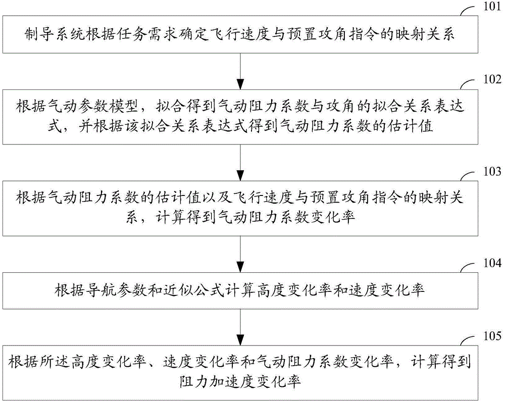
[0037] figure 1 It is a schematic flow chart of the method for determining the drag acceleration change rate used for the reentry guidance of the lift aircraft in the embodiment of the present invention. Such as figure 1 As shown, the method for determining the rate of change of drag acceleration for re-entry guidance of a lift-type aircraft in the embodiment of the present invention mainly includes the following steps:

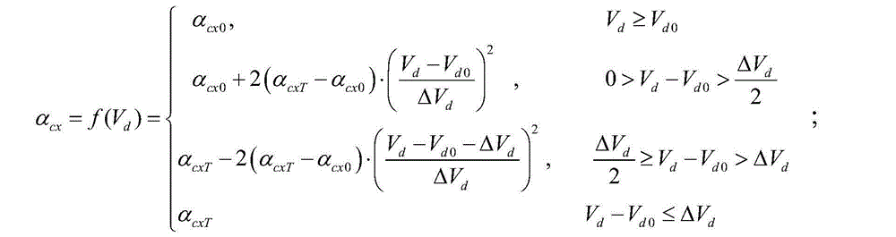
[0038] Step 101, determine the mapping relationship between flight speed and preset angle of attack command according to mission requirements.

[0039] Since hypersonic aircraft generally fly wi...


PUM


Abstract

The invention discloses a method for determining the lift aircraft reentry guidance resistance accelerated speed change rate. The method includes the steps that a mapping relation between the flight speed and a preset attack angle command is determined according to a task requirement; according to a pneumatic parameter model, fitting is carried out to obtain a fitting relational expression between a pneumatic resistance parameter and an attack angle, and an estimation value of the pneumatic resistance parameter is obtained according to the fitting relational expression; according to the estimation value of the pneumatic resistance parameter and the mapping relation between the flight speed and the preset attack angle command, the pneumatic resistance coefficient change rate is obtained through calculation; the height change rate and the speed change rate are calculated according to a navigation parameter and an approximation formula; according to the height change rate, the speed change rate and the pneumatic resistance coefficient change rate, a resistance accelerated speed change rate is obtained through calculation. By means of the method, influences of sampling noise on the reentry guidance control accuracy can be effectively avoided, and the tracking control accuracy of the resistance accelerated speed is improved.

Description

technical field [0001] The invention relates to the field of aerospace technology, in particular to a method for determining the rate of change of resistance acceleration for reentry guidance of a lift-force aircraft. Background technique [0002] Lift-type re-entry guidance technology is a core key technology in the development of hypersonic vehicles. This technology can alleviate harsh conditions such as heat protection, aerodynamics and overload during high-dynamic re-entry flight, and guide the aircraft to a predetermined area. In the prior art, the drag acceleration tracking guidance method is a relatively mature reentry guidance method, which has been widely used in space shuttles and hypersonic glide vehicles in the United States. This method realizes the management of the kinetic energy of the aircraft through the tracking control of the drag acceleration profile, has good adaptability to the atmospheric density and altitude navigation errors, and can realize the ene...

Claims


Application Information

Patent Timeline
Patent Type & Authority Applications(China)
IPC IPC(8): B64G1/24
Inventor 吴浩杨业郭涛梁波梁禄扬周峰刘茜筠
Owner BEIJING AEROSPACE AUTOMATIC CONTROL RES INST
Why Eureka
Try Eureka