
Mortise and tenon spring lock cylinder

A mortise-and-mortise type, lock cylinder technology, used in cylinder marble locks, construction locks, locks with turning keys, etc. "Bump key" to unlock); non-this lock key can be entered, etc., to achieve the effect of high safety factor and reduce the probability of hitting the key to unlock the lock

Active Publication Date: 2017-05-17
高岗
View PDF5 Cites 0 Cited by
  • Summary
  • Abstract
  • Description
  • Claims
  • Application Information

AI Technical Summary

Problems solved by technology

However, the disadvantages are becoming more and more obvious. There are three main aspects: the end of the pin is exposed and the working stroke is short. Accessible to the lock cylinder, it is easy to cause mutual opening of keys and unequal key teeth, etc.; the key can be freely configured, and the key matching process is simple. With a key mold of a tumbler lock, the door can be easily opened within ten seconds with tin foil installed; Unlock the lock violently, twist off the pin, it is easy to open the lock

Method used


Image

  • Mortise and tenon spring lock cylinder
  • Mortise and tenon spring lock cylinder
  • Mortise and tenon spring lock cylinder

Examples


Embodiment 1

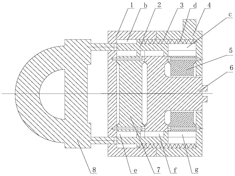
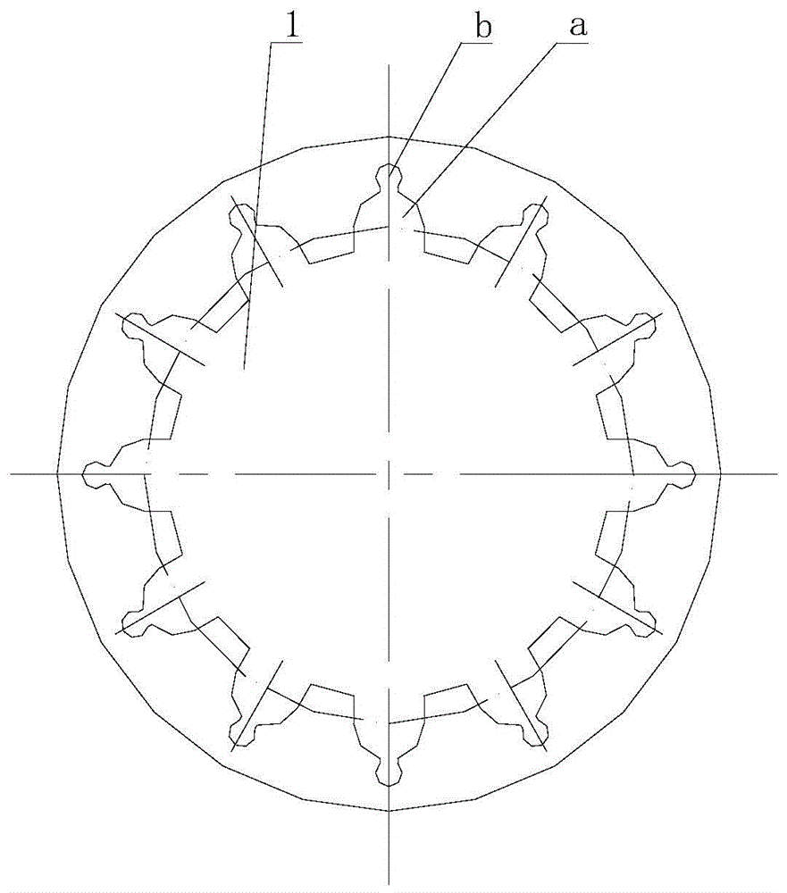
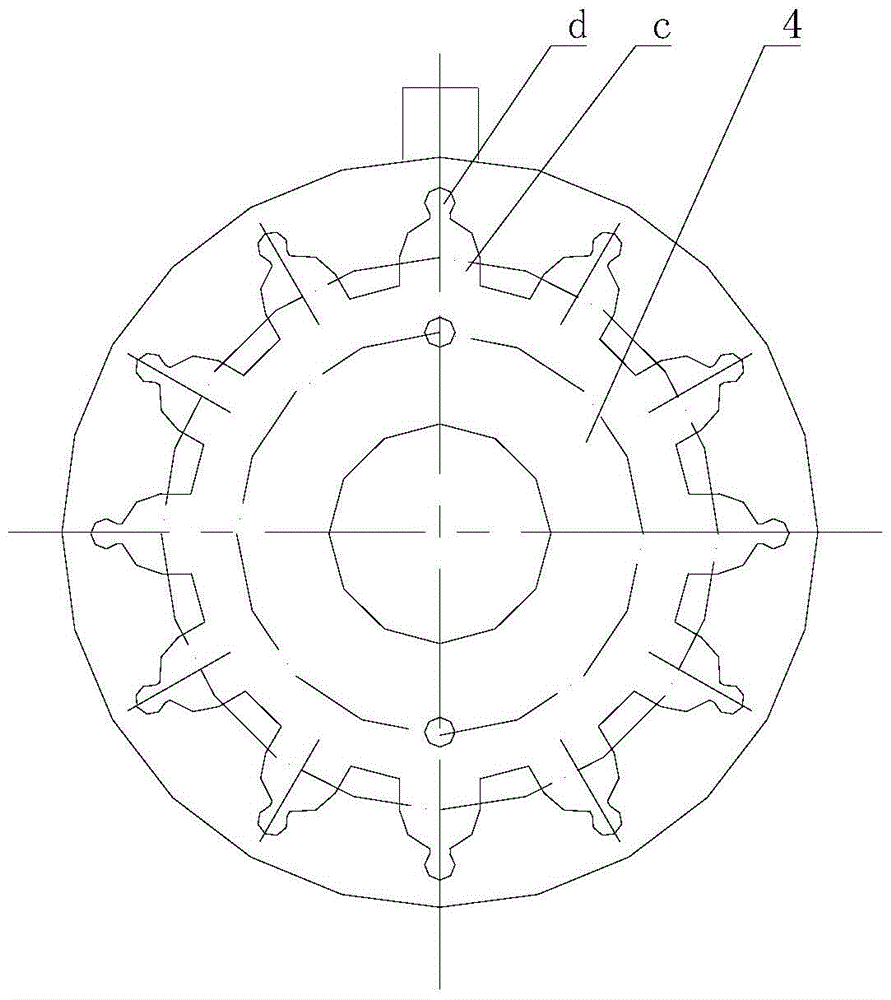
[0014] exist figure 1 , 2 , 3, and 4, the mortise and tenon type rebound sub-lock cylinder of the present invention consists of a front lock cylinder cover 1, a marble 2, a spring 3, a rear lock cylinder cover 4, a rear inner lock cylinder pad 5, an inner lock cylinder body 6, a front inner The lock core pad 7 and the key 8 are connected to form. The inner side wall of the front lock cylinder cover 1 is processed with 12 first grooves a that equally divide the circumference. It is a circular second groove b, and the bottom of the front lock cylinder cover 1 is processed with 12 circular through holes that equally divide the circumference as keyholes, and the keyholes are used to insert the key 8. There are 12 cylinders corresponding to the keyhole processed in the direction, and the pin 2 is installed in the first groove a. The geometric shape of the pin 2 is F-shaped. The table is stuck in the second slot b, and the center position of the inner bottom of the front lock cyl...

Embodiment 2

[0017] In this embodiment, the inner side wall of the front lock cylinder cover 1 is processed with 10 first grooves a that equally divide the circumference. The bottom of a is processed with a groove b with a circular cross section, and the bottom of the front lock cylinder cover 1 is processed with 10 circular through holes that equally divide the circumference as keyholes. A key 8 is arranged in the keyhole, and the structure of the key 8 is a circle. 10 cylinders corresponding to the key holes are processed on the disk along the circumferential direction, and the center position of the inner bottom of the front lock cylinder cover 1 is fixed with a threaded fastening connector to install the front inner lock cylinder pad 7, and the front inner lock cylinder pad 7 The geometric shape is cylindrical, and the cylindrical outer surface is processed with 10 fifth through grooves e that equally divide the circumference. The vertical section of the fifth through groove e is rectan...

Embodiment 3

[0019] In this embodiment, the inner side wall of the front lock cylinder cover 1 is processed with two first grooves a that equally divide the circumference. The bottom of a is processed with a groove b with a circular cross section, and the bottom of the front lock cylinder cover 1 is processed with two circular through holes corresponding to the first groove a as key holes, and a key 8 is arranged in the key hole. The structure of 8 is that two cylinders corresponding to the key holes are processed on the disc along the circumferential direction, and the center position of the inner bottom of the front lock cylinder cover 1 is fixedly installed with a front inner lock cylinder pad 7 with a threaded fastening connector. The geometric shape of the lock cylinder pad 7 is cylindrical, and the cylindrical outer surface is processed with 2 fifth through grooves e that equally divide the circumference. The vertical section of the fifth through groove e is rectangular, and the front...


PUM


Abstract

The invention relates to a mortise and tenon type reverse cylinder lock core. Key holes are formed in the bottom of a front lock cylinder cover, grooves a are machined in the inner side wall, grooves b are formed in the bottoms of the grooves a, a key is arranged in the key holes, and cylinders are installed in the grooves a; a front inner lock core pad is fixedly installed in the center of the bottom in the front lock cylinder cover and in a cylindrical geometrical shape, through grooves e are formed in the cylindrical outer surface, an inner lock core body is placed on the front lock core pad, a lock core shaft is machined in the center of a disc of the bottom of the lock core body, the tail end of the lock core shaft is machined into a circular cylinder with the diameter smaller than that of the lock core shaft, grooves are machined in the circular cylinder, through grooves f are machined in the side face of the disc at the bottom of the inner lock core body, and a rear inner lock core pad and a rear lock core cover are sequentially installed on the lock core shaft of the inner lock core body; the rear inner lock core pad is fixedly installed on the rear lock core cover, through grooves g are machined inn the side face of the rear inner lock core pad, grooves c are formed in the inner side wall of the rear lock core cover, and grooves d are machined in the bottoms of the grooves c; spring grooves are formed by the grooves b and the grooves d and provided with springs, and cylinder grooves are formed by the grooves a and the grooves c.

Description

technical field [0001] The invention belongs to the technical field of locks, and in particular relates to a mortise and tenon type rebound lock cylinder. Background technique [0002] In 1848, the American Yale Linus invented the pin lock with a cylindrical pin. The pin lock is also called pin ball lock, bead lock, bead lock, bolt lock or pin lock. It is the most common lock structure. The principle is to use multiple cylindrical parts of different heights (called lock springs, pins or beads) to lock the lock cylinder. When the correct key is put in, each lock spring is pushed to the same height, and the lock cylinder is released. At present, this structure is widely used in the world. The structure of modern pin locks has new developments, and there are two-way, three-way, four-way pins, mother pins and other structures, as well as flat, double-sided, multi-sided, double-row double-sided, multi-row multi-sided pin pin structures and combined pin pin structures. Thereby t...

Claims


Application Information

Patent Timeline
Patent Type & Authority Patents(China)
IPC IPC(8): E05B27/00E05B19/14E05B15/14E05B15/00
Inventor 高岗
Owner 高岗
Learn More