
Shredded paper pulp stirring mechanism

A stirring mechanism and pulp technology, applied in the direction of mixer accessories, mixers, dissolving, etc., can solve the problems of affecting papermaking efficiency and inconvenient stirring

Inactive Publication Date: 2015-09-09
赵静
View PDF6 Cites 0 Cited by
  • Summary
  • Abstract
  • Description
  • Claims
  • Application Information

AI Technical Summary

Problems solved by technology

The existing pulp is inconvenient to stir, and the beating part is uniform, which affects the efficiency of papermaking

Method used


Image

  • Shredded paper pulp stirring mechanism
  • Shredded paper pulp stirring mechanism

Examples


Embodiment Construction

[0012] The preferred embodiments of the present invention will be described in detail below in conjunction with the accompanying drawings, so that the advantages and features of the present invention can be more easily understood by those skilled in the art, so as to define the protection scope of the present invention more clearly.

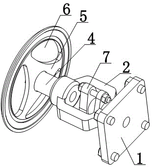
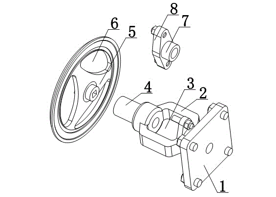
[0013] Such as figure 1 and figure 2 As shown, a shredded pulp stirring mechanism includes a driving plate 1, the driving plate 1 is provided with a connecting frame 2, the connecting frame 2 is provided with a mounting groove 3, the connecting frame 2 is provided with a driving tube 4, and the end of the driving tube 4 is sleeved with The stirring plate 5 is provided with a stirring tank 6; the installation tank 3 is provided with a docking pipe 7, and the docking pipe 7 is provided with a docking block 8; the stirring plate 5 is in the shape of a disc.

[0014] The shredded pulp mixing mechanism of the present invention can be docked with the...


PUM


Abstract

The invention discloses a shredded paper pulp stirring mechanism. The shredded paper pulp stirring mechanism comprises a driver board; the driver board is provided with a connecting support; the connecting support is provided with an installation groove and a driving tube; the end part of the driving tube is sleeved with a stirring disc; and the stirring disc is provided with stirring grooves. Abutting joint of the shredded paper pulp stirring mechanism with a driving shaft can be realized via the drive board; the driving shaft can be arranged on a middle part of the drive board; the driving shaft is externally connected with a driving motor; and the drive board is controlled to rotate by the driving motor, so that it is convenient for realizing of stirring of the stirring disc.

Description

technical field [0001] The invention relates to a stirring mechanism, in particular to a shredded pulp stirring mechanism. Background technique [0002] Pulp is a fibrous substance made from plant fibers through different processing methods. It can be divided into mechanical pulp, chemical pulp and chemical mechanical pulp according to the processing method; it can also be divided into wood pulp, straw pulp and hemp pulp according to the fiber raw materials used. Pulp, reed pulp, cane pulp. The existing pulp is inconvenient to stir, and the beating part is uniform, which affects the papermaking efficiency. Contents of the invention [0003] The present invention mainly solves the technical problems existing in the prior art, thereby providing a drive plate that can be docked with the drive shaft, the drive shaft can be installed in the middle of the drive plate, the drive shaft is externally connected to the drive motor, and the drive plate is controlled by the drive mot...

Claims


Application Information

Patent Timeline
IPC IPC(8): B01F15/00
Inventor 赵静
Owner 赵静
Learn More