Packaging equipment possessing arc edge fingerprint identification chip and packaging and cutting method

A technology for fingerprint identification and packaging equipment, applied in electrical components, semiconductor/solid-state device manufacturing, circuits, etc., can solve the problems of uneven thickness of the chip surface coating, low yield rate, etc., to ensure smoothness, smooth and tidy arc edges Effect

Active Publication Date: 2015-09-16
深圳市东方聚成科技有限公司
View PDF5 Cites 9 Cited by
  • Summary
  • Abstract
  • Description
  • Claims
  • Application Information

AI Technical Summary

Problems solved by technology

[0006] The invention provides a packaging device, which aims to solve the prob

Method used


Image

  • Packaging equipment possessing arc edge fingerprint identification chip and packaging and cutting method
  • Packaging equipment possessing arc edge fingerprint identification chip and packaging and cutting method
  • Packaging equipment possessing arc edge fingerprint identification chip and packaging and cutting method

Examples


Embodiment 1

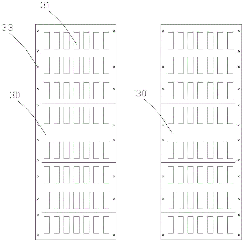
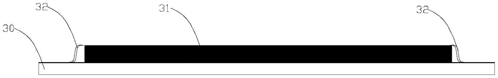
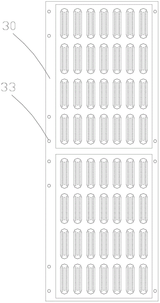
[0034] Embodiment one, with reference to Figure 1-9As shown, the embodiment of the present invention provides a packaging device with an arc-edge fingerprint identification chip, including a pair of molds, the mold is divided into an upper mold 20 and a lower mold 10, and the lower mold 10 is provided with a PCB board that can accommodate slot 11, the PCB board 30 is a whole PCB board with multiple groups of fingerprint identification devices 31 welded, and the upper mold 20 is provided with a circle that can accommodate the identification devices 31 and is consistent with the shape of the fingerprint chip. Shaped or elliptical or flat elliptical cavity 21 with arc edges, the cavity 21 is set corresponding to the fingerprint identification device 31 on the PCB 30, and the cavity 21 is connected to the package through the hot runner 40 The material injection port 50 is connected, the hot runner 40 is divided into a main channel 41 and a branch channel 42, the main channel 41 c...

Embodiment 2

[0036] Embodiment two, refer to Figure 1-9 As shown, this embodiment also provides a packaging and cutting method for fingerprint identification chips with arc edges, using the packaging equipment described in the first embodiment above, the specific steps are as follows:

[0037] Step 1, placing the PCB board 30 into the slot 11 of the lower mold 10, and positioning the PCB board 30 after passing the positioning column 13 through the positioning hole 33;

[0038] Step 2, fastening the upper mold 20 to the lower mold 10 through the positioning pin 22;

[0039] Step 3: vacuumize the mold, heat the mold and keep it at a certain temperature, and then inject packaging material from the injection port 50, and the packaging material enters the injection port 50 in a high-temperature liquid state Enter the main flow channel 41 and the branch flow channel 42 in sequence, gradually reduce the injection pressure and inject into the gap between the cavity 21 and the identification devi...

Embodiment 3

[0047] Embodiment 3, this embodiment also provides a method for encapsulating and cutting a circular fingerprint identification chip, using the encapsulation equipment described in the above-mentioned embodiment 1, the difference from the above-mentioned embodiment is that the identification chip that needs to be produced is Circular, so it is necessary to set a plurality of said branch channels 42 to communicate with the side of the cavity, and it is necessary to keep the flow channels at the communication places relatively thin, so as to make it easier to leave a small gap when laser cutting is used in the cutting process. Burnt surface.


PUM

PropertyMeasurementUnit
Surface thicknessaaaaaaaaaa
Thicknessaaaaaaaaaa

Abstract

The invention provides packaging equipment possessing an arc edge fingerprint identification chip. The equipment comprises a pair of dies. The dies are divided into an upper die and a lower die. A slot position which can accommodate a PCB is arranged in the lower die. The PCB is an entire PCB on which multiple groups of fingerprint identification devices are welded. The upper die is provided with circular or oval or flat oval cavities which can accommodate the identification devices, have a consistent shape with the fingerprint chip and possess arc edges. The cavity and the fingerprint identification devices on the PCB are correspondingly arranged. The cavities are connected to a packaging material injection port through a hot runner. The hot runner is divided into a main runner and a branch runner. The main runner is connected to the injection port. The branch runner is connected to side edges of the cavities. A distance between an inner surface of the upper die and a slot position bottom surface is equal to a thickness of the PCB. A depth of the cavities is greater than a height from the PCB surface to an upper surface of the identification devices.

Description

technical field [0001] The invention belongs to the technical field of packaging of electronic devices, and in particular relates to packaging equipment and a production method of a fingerprint chip. Background technique [0002] Fingerprint recognition technology has been widely used at present. It is involved in attendance machines, security access control, and port customs clearance. Now mobile phones are gradually using fingerprint recognition technology to start and unlock devices. This type of fingerprint recognition The technology uses a capacitive fingerprint identification chip, which does not require light source collection and has the advantage of being ultra-thin and ultra-small. It is usually installed on the button of a mobile phone, and a layer of plastic is covered on it for anti-wear protection and line protection. Here it is required Describe the structure of the capacitive fingerprint recognition chip. This kind of chip is mainly welded on the PCB board by...

Claims


Application Information

Patent Timeline
IPC IPC(8): H01L21/50H01L21/56
CPCH01L21/50H01L21/52H01L21/56H01L21/565
Inventor 林梓梁
Owner 深圳市东方聚成科技有限公司
Why Eureka
Try Eureka