mechanical seal

A technology of mechanical sealing device and sealing ring, which is applied in the direction of engine sealing, mechanical equipment, engine components, etc., can solve the problems of sealing gap leakage, mechanical sealing device failure, etc., to reduce leakage rate, improve axial movement, improve shaft The effect of direction following performance

Active Publication Date: 2019-11-26
EAGLEBURGMANN GERMANY GMBH &CO KG
View PDF8 Cites 0 Cited by
  • Summary
  • Abstract
  • Description
  • Claims
  • Application Information

AI Technical Summary

Problems solved by technology

These aforementioned problems can lead to increased leakage at the sealing gap during operation, up to the failure of the mechanical seal

Method used


Image

  • mechanical seal
  • mechanical seal
  • mechanical seal

Examples


Embodiment Construction

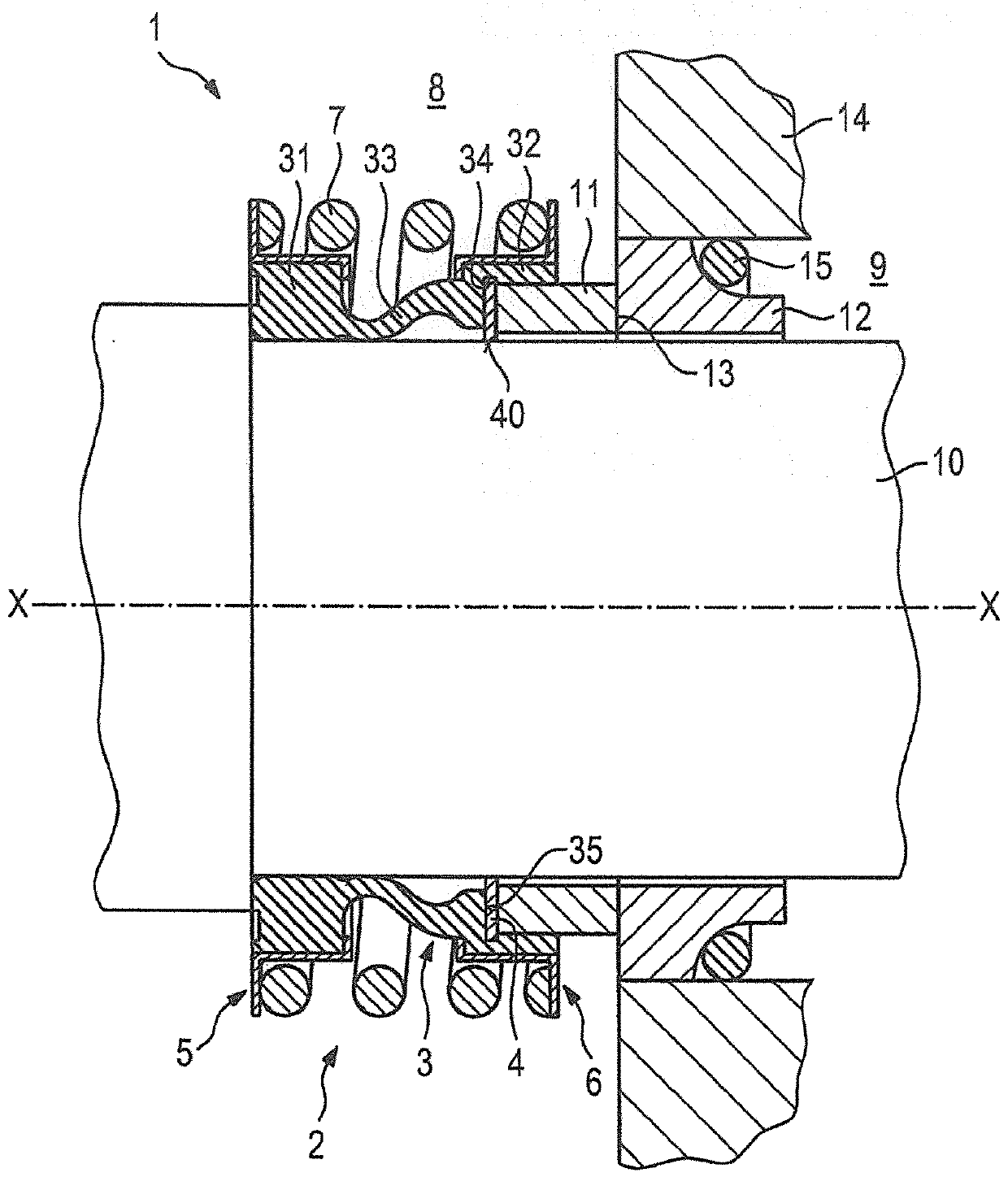
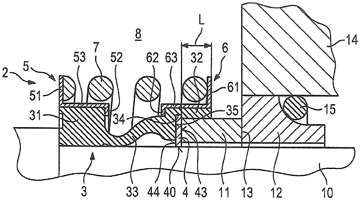
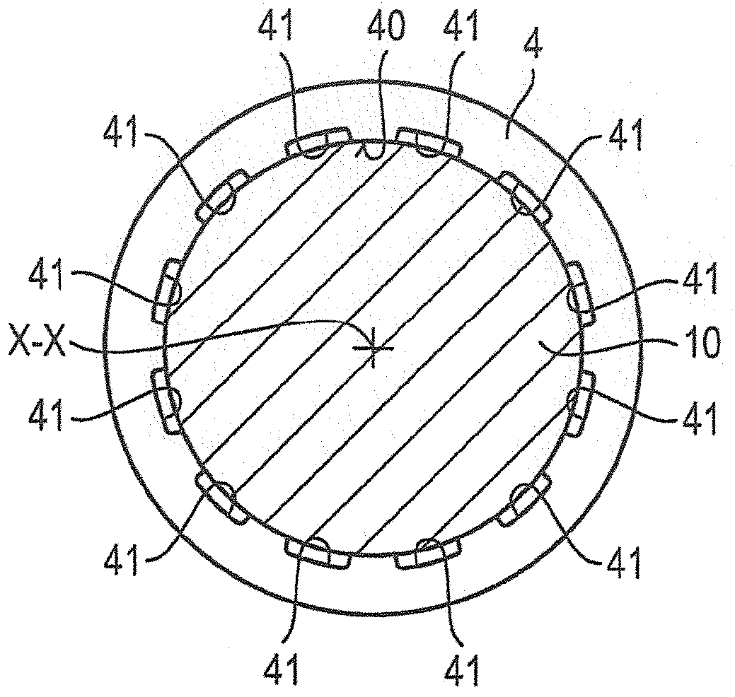
[0033] Refer to the following Figures 1 to 3 The mechanical seal device 1 according to the first embodiment of the present invention has been described in detail.

[0034] Such as figure 1 It is clear that the mechanical seal arrangement 1 comprises a rotating sealing ring 11 and a stationary sealing ring 12 which define a sealing gap 13 between them in a known manner. The mechanical sealing device 1 is used for sealing the first space 8 and the second space 9 .

[0035] The rotary sealing ring 11 is connected to and rotates with a rotating member 10 , which in this embodiment is a shaft. The stationary sealing ring 12 is connected to a stationary housing 14 . Reference numeral 15 denotes an auxiliary seal for sealingly fixing the sealing ring 12 relative to the housing 14 .

[0036] The mechanical seal arrangement 1 also comprises a bellows unit 2 which establishes the connection between the rotary seal ring 11 and the rotary component 10 . The bellows unit 2 comprises ...


PUM


Abstract

The invention relates to a mechanical sealing device, which comprises: a rotating sealing ring (11) and a stationary sealing ring (12), the rotating sealing ring (11) and the stationary sealing ring (12) A sealing gap (13) is defined therebetween; and a bellows unit (2), which has a bellows piece (3) and a gasket (4), wherein the bellows piece (3) has a first connection area (31), a second The connection area (32) and the bellows middle area (33), wherein the bellows piece (3) is made of elastomeric material and provides the connection between the rotating sealing ring (11) and the rotating member (10), wherein the gasket (4) It is arranged between the bellows piece (3) and the rotating sealing ring (11), and the inner peripheral area (40) of the gasket (4) is arranged for bearing on the rotating member (10).

Description

technical field [0001] The invention relates to a mechanical seal with a bellows element which has improved axial followability during operation. Background technique [0002] Mechanical seals with bellows elements are known in various designs from the prior art. The bellows element can in principle be an elastomer bellows or a metal bellows, which in particular enable an axial follow-up of the mechanical seal, for example, in the event of a shaft deflection. It has been established here that, in particular when using elastomer bellows, a degraded follow-up behavior of the mechanical seal can result. The reason for this is on the one hand that, due to the flexibility of the elastomer material, the supporting shoulder of the bellows can adhere to the shaft surface or the like and thus cannot follow the axial follow-up quickly enough. The above-mentioned problems arise even more if, for example, dirt is present on the shaft surface, which can be caused by deposits on the sha...

Claims


Application Information

Patent Timeline
Patent Type & Authority Patents(China)
IPC IPC(8): F16J15/34
CPCF16J15/344F16J15/32F16J15/34F16J15/3464F16J15/36
Inventor 迪特尔·泽根拜因W·里斯R·席克坦茨约尔格·泰勒科R·沃泊瓦A·艾特兹P·哈斯勒巴撤E·博斯特曼
Owner EAGLEBURGMANN GERMANY GMBH &CO KG
Why Eureka
Try Eureka