
Apparatus for granulating hot cut

A technology of hot-cut pellets and pellets, which is applied to household components, household appliances, and other household appliances. It can solve the problems of brittle seals, leakage, and no longer guaranteed axial mobility of the shaft, and achieve the effect of short life.

Active Publication Date: 2011-11-23
EREMA ENG RECYCLING MASCH & ANLAGEN GMBH
View PDF6 Cites 3 Cited by
  • Summary
  • Abstract
  • Description
  • Claims
  • Application Information

AI Technical Summary

Problems solved by technology

In addition, the sleeve bearing structure requires a certain cost
The continuous grinding support of the shaft in the box uses two sealing rings with an oil film between them, which is also disadvantageous, that is, once the life of the seal is exhausted, the seal becomes brittle or leaks, the oil film stops, and the shaft is bitten. Axial mobility is no longer guaranteed

Method used


Image

  • Apparatus for granulating hot cut
  • Apparatus for granulating hot cut
  • Apparatus for granulating hot cut

Examples


Embodiment Construction

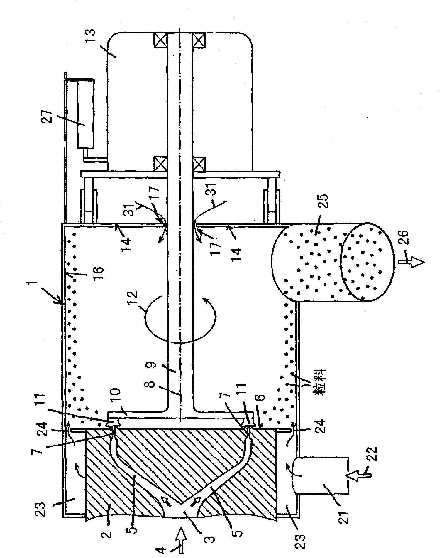
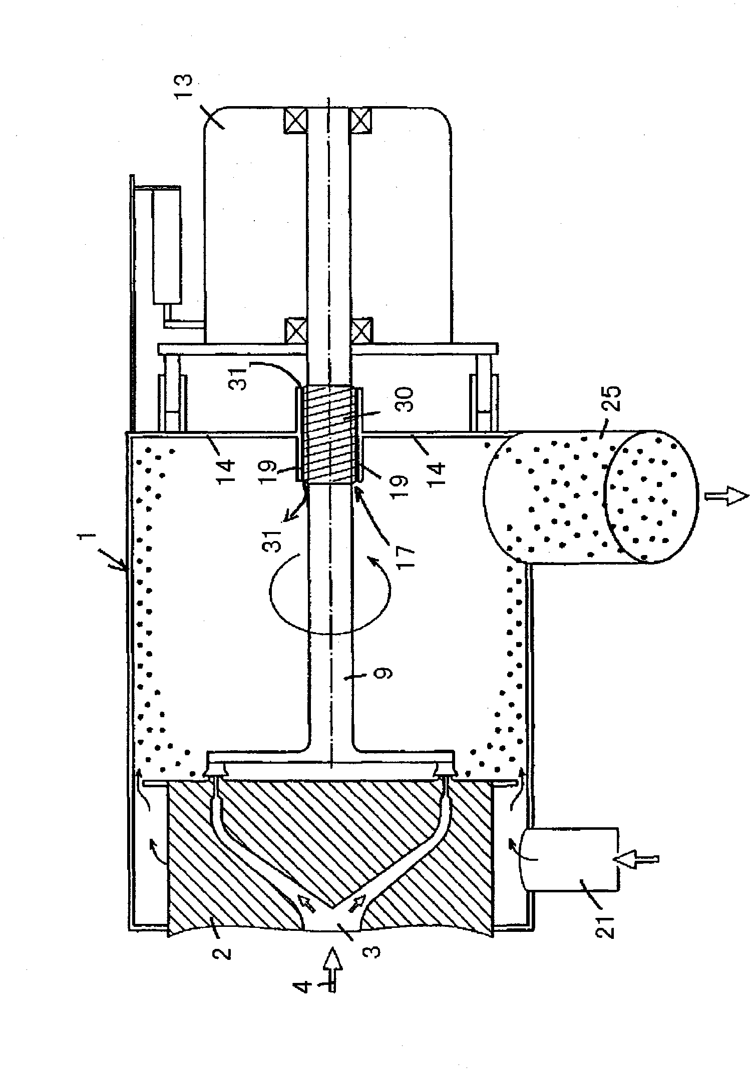
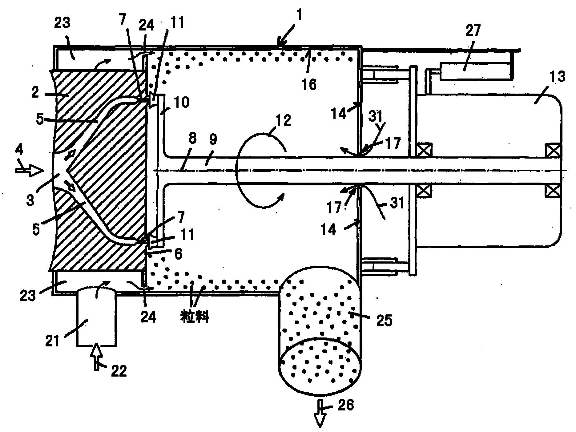
[0025] figure 1 An advantageous embodiment of the device shown has a cylindrical pelletizing box 1 which is delimited at its front end, in particular facing the extruder, by a perforated plate 2 and at its corresponding front end by an end wall 14 . In the perforated plate 2 there is provided a feed channel 3 for the pelletized plasticized material or melt, in particular a thermoplastic, from which the thermoplastic flows in the direction of the arrow 4 into a plurality of distribution channels 5 , which flow in the orifice The end face 6 of the plate 2 opens into nozzles 7 which are arranged circularly and equidistantly around the central longitudinal axis 8 of the granulation tank 1 .

[0026] The longitudinal axis 8 simultaneously forms the axis of rotation of the shaft 9, which has a cutter head 10 at its end facing the orifice plate 2, which is equipped with a plurality of cutting knives 11, which are arranged on the axis of the shaft 9 around its axis. The arrow directi...


PUM


Abstract

The invention relates to an apparatus for granulating hot cut, in particular thermoplastic resin material, the material strands melted by an extruder being knocked off into granule pellets in a granulating housing (1) by rotating knives (11) disposed on a shaft (9) driven by way of a motor (13), the granule pellets being picked up by a cooling medium flowing in the granulating housing (1), cooled and discharged out of the granulating housing (1), characterized in that a flow opening (17) establishing a continuous fluid connection between the inside of the granulating housing (1) and the outside environment is designed between the shaft (9) and the region of the granulating housing (1) in which the shaft (9) penetrates the granulating housing (1).

Description

technical field [0001] The invention relates to a granulation device according to the preamble of claim 1 . Background technique [0002] Pelletizers for hot-cut pellets, which collect, cool and discharge the cut pellets by means of a rapidly flowing liquid film or ring, such as water, are known in different designs. The key part of this type of device is the sealing of the cutter shaft to the constantly rotating water in the pelletizing box. This means avoiding water running out of the area between this shaft and the pelletizing box, otherwise the water will flow into the area of ​​the motor and cause trouble. For this reason, the prior art proposes a wide variety of seals in order to seal off a shaft constantly rotating about its axis as reliably as possible. [0003] The situation becomes more difficult if the shaft not only rotates about its own axis, but also moves axially to adjust the cutter-to-orifice distance and optimally match the cutting pressure of the cutter....

Claims


Application Information

Patent Timeline
Patent Type & Authority Applications(China)
IPC IPC(8): B29B9/06
CPCB29B9/06B29B9/065B29C48/0022B29C48/04B29C48/05B29C48/14B29C48/345B29C48/86Y10S425/06Y10S425/23B29B11/02
Inventor K·费克廷格M·哈克尔G·温德林
Owner EREMA ENG RECYCLING MASCH & ANLAGEN GMBH
Learn More