Supercharge Your Innovation With Domain-Expert AI Agents!

Methods for end-user parallax adjustment

A parallax and parallax correction technology, applied in color TV parts, TV system parts, TV and other directions, can solve problems such as improper correction of parallax error, distance to target or insufficient correction of parallax in factory calibration

Active Publication Date: 2015-10-28
弗兰克公司
View PDF5 Cites 2 Cited by
  • Summary
  • Abstract
  • Description
  • Claims
  • Application Information

AI Technical Summary

Problems solved by technology

In any case, however, situations may arise where focus, distance to target, or factory calibration parallax corrections are insufficient and parallax errors are not properly corrected

Method used


Image

  • Methods for end-user parallax adjustment
  • Methods for end-user parallax adjustment
  • Methods for end-user parallax adjustment

Examples


Embodiment Construction

[0016] The following detailed description is exemplary in nature and is not intended to limit the scope, applicability, or configuration of the invention in any way. Rather, the following description provides some practical illustrations for implementing examples of the invention. Examples of configurations, materials, dimensions, and manufacturing processes for selected elements are provided, and all other elements employ what is known to one of ordinary skill in the field of the invention. Those skilled in the art will recognize that there are various suitable alternatives to many of the described examples.

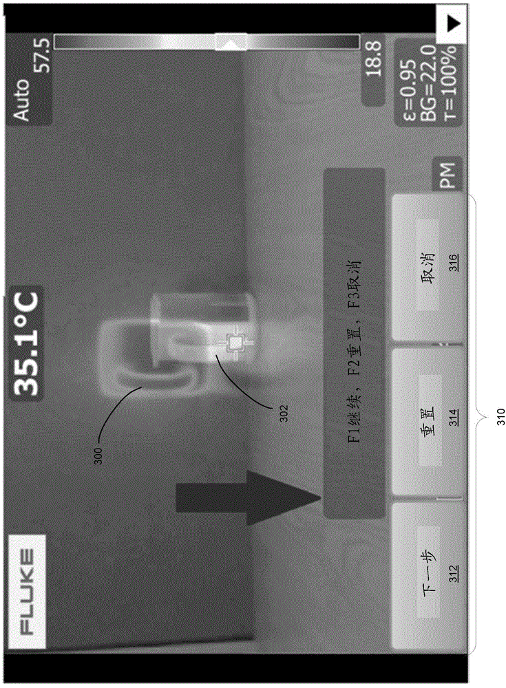
[0017] Thermal imaging cameras may be used to detect heat maps across a scene under observation (including one or more objects). A thermal imaging camera detects infrared radiation emitted by a scene and converts this infrared radiation into an infrared image indicative of a heat map. In certain embodiments, a thermal imaging camera may also capture visible light from...


PUM


Abstract

A thermal imaging system having visible light and infrared camera modules can perform various methods for reducing parallax errors between captured visible light and infrared images. The system can perform a first calibration method, which can be manual or automatic, and can receive subsequent parallax refinement adjustments via a user interface. The parallax refinement adjustments may be stored in memory for future use. Systems can include an add-on lens capable of interfacing with the infrared camera module for producing modified infrared images. The system can perform methods to reduce parallax between modified infrared and visible light images, and can receive subsequent parallax refinement adjustments to further reduce parallax between the modified infrared and visible light images. The add-on lens parallax refinement data can be stored in memory of the camera memory of the lens for future use in parallax correction.

Description

Background technique [0001] Thermal imaging cameras are used in a variety of situations. For example, thermal imaging cameras are often used to thermally inspect equipment during maintenance inspections. Exemplary equipment may include rotating machinery, switchboards, or banks of circuit breakers, among other types of equipment. Thermal inspections can use infrared (IR) energy detection to detect hot spots in equipment, such as overheated machinery or electrical components, helping to ensure that overheated equipment is repaired or replaced in a timely manner before more significant problems develop. [0002] Depending on the configuration of the camera, a thermal imaging camera can also produce a visible light image of the same object. The cameras can display infrared images and visible light images in a coordinated manner, for example, to aid an operator in interpreting thermal images generated by a thermal imaging camera. Unlike visible light images, which generally pro...

Claims


Application Information

Patent Timeline
Patent Type & Authority Applications(China)
IPC IPC(8): H04N5/232H04N5/217
CPCH04N13/0246H04N5/2258H04N5/23216H04N5/23293H04N5/33H04N5/332H04N13/0007H04N13/106H04N13/246H04N23/45H04N23/62H04N23/631H04N23/11
Inventor J.里德T.J.麦克芒努斯
Owner 弗兰克公司
Features
  • R&D
  • Intellectual Property
  • Life Sciences
  • Materials
  • Tech Scout
  • Unparalleled Data Quality
  • Higher Quality Content
  • 60% Fewer Hallucinations
Learn More