
nox measurement system and method

A measurement system and measurement pipeline technology, applied in the field of NOx measurement system, can solve the problems of shortening the service life of NOx sensors, blockage of bypass pipelines, etc.

Active Publication Date: 2016-08-17
WARTSILA FINLAND OY
View PDF5 Cites 0 Cited by
  • Summary
  • Abstract
  • Description
  • Claims
  • Application Information

AI Technical Summary

Problems solved by technology

When exhaust gas condenses on cold surfaces, sulfuric acid is formed which can plug the bypass line and shorten the life of the NOx sensor

Method used


Image

  • nox measurement system and method
  • nox measurement system and method
  • nox measurement system and method

Examples


Embodiment Construction

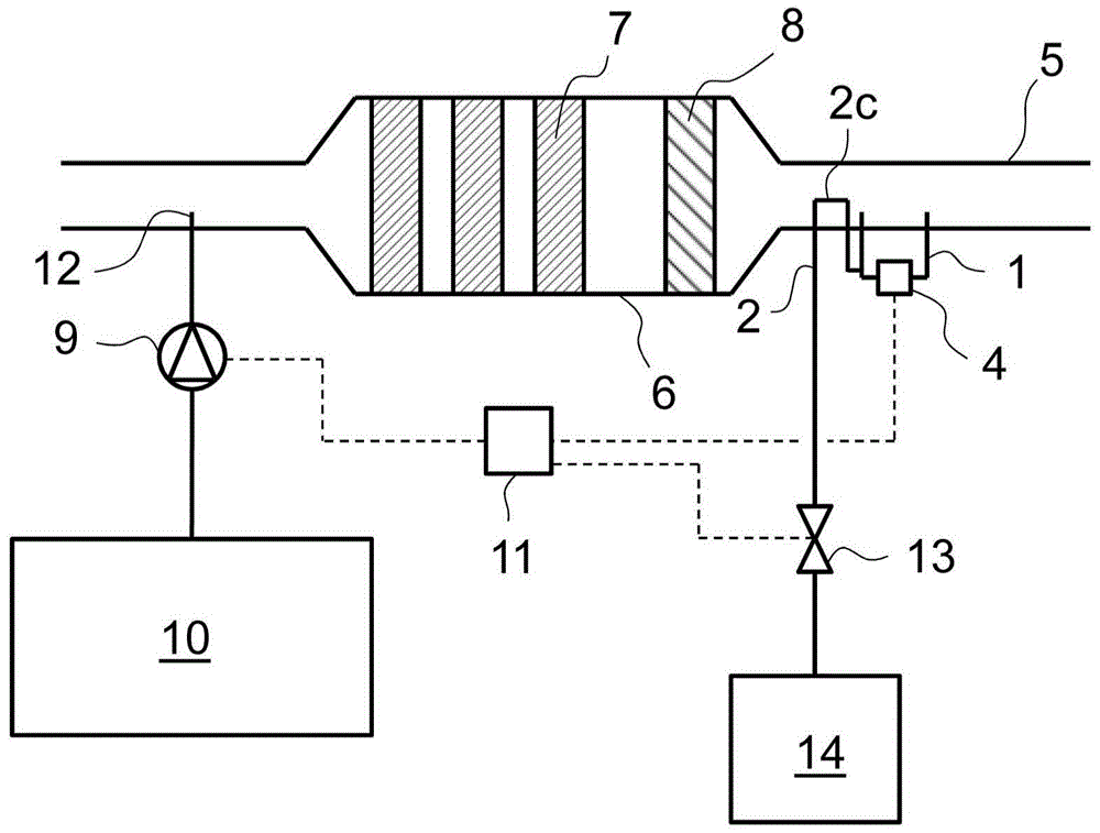
[0014] exist figure 1 , a simplified schematic diagram of a selective catalytic reduction (SCR) system of an internal combustion engine is shown. The SCR system is particularly suitable for large piston engines, such as the main or auxiliary engines of ships or engines used in power plants to generate electricity. The system includes a catalytic converter 6 with three SCR elements 7 . The SCR element 7 is a ceramic honeycomb structure coated with catalyst material. Urea, which is used as a reducing agent, is injected into the exhaust gas flow upstream of the catalytic converter 6 via a reducing agent injector 12 . Urea is stored in tank 10 and the correct amount of urea solution is delivered to reductant injector 12 using metering pump 9 . The control unit 11 is arranged to control the metering pump 9 . The urea injected into the exhaust system mixes with the exhaust gas and is decomposed into ammonia and carbon dioxide due to the heat of the exhaust gas. On the surface o...


PUM

PropertyMeasurementUnit
angleaaaaaaaaaa

Abstract

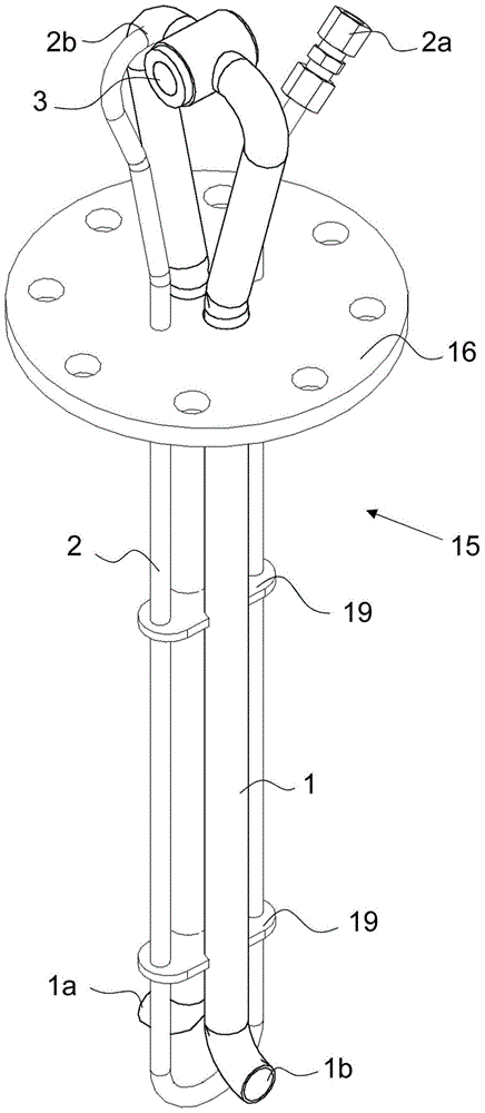
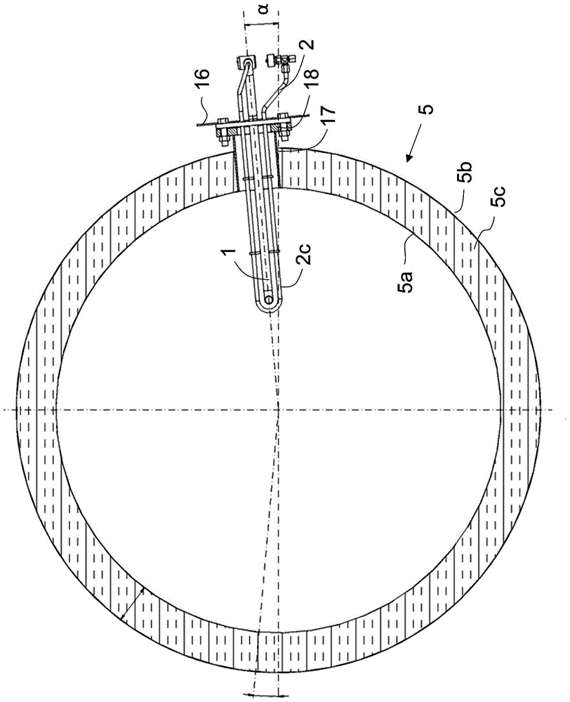
The NOx measurement system for an internal combustion engine comprises a measurement duct (1), a NOx-sensor (4), which is arranged in the measurement duct (1), a purging duct (2), which is connected to the measurement duct (1) for introducing pressurized air into the measurement duct (1), and means (2c) for heating the measurement duct (1).

Description

technical field [0001] The invention relates to a NOx measurement system for an internal combustion engine. The invention also relates to a method for measuring the NOx concentration in the exhaust gas of an internal combustion engine. Background technique [0002] Selective catalytic reduction (SCR) systems are becoming more common due to increasing regulation of nitrogen oxide (NOx) emissions from internal combustion engines in ships and power plants. In SCR systems, correct dosage of reductant (usually urea) is very important to achieve effective NOx reduction and avoid ammonia slip. To improve reductant dosing accuracy, the SCR system can be equipped with a NOx sensor that measures the NOx concentration downstream of the SCR element. [0003] Patent application WO 2008 / 43928A1 discloses an SCR system for vehicles in which a NOx sensor is placed downstream of the SCR catalyst and continuously monitors the NOx and ammonia concentrations of the exhaust. According to this...

Claims


Application Information

Patent Timeline
Patent Type & Authority Patents(China)
IPC IPC(8): B01D53/94F01N3/20F01N3/30G01N27/419
CPCF01N3/2066F01N3/306F01N2560/026F01N2560/20F01N2610/02F01N2610/148Y02T10/12
Inventor M·勒夫霍姆D·诺德伯格S·格兰霍姆
Owner WARTSILA FINLAND OY
Learn More