Supercharge Your Innovation With Domain-Expert AI Agents!

Partition wall system including clamping of the panels

A panel, elastic clamping technology, applied in the direction of wall, window glass installation, parallel glass structure, etc., can solve the problem of incompatibility between size and material selection

Active Publication Date: 2015-11-18
MAARS HLDG BV
View PDF5 Cites 1 Cited by
  • Summary
  • Abstract
  • Description
  • Claims
  • Application Information

AI Technical Summary

Problems solved by technology

However, the subsequent use of various additional components is at odds with the preferred size and material selection of modular partition walls made of standard components.

Method used


Image

  • Partition wall system including clamping of the panels
  • Partition wall system including clamping of the panels
  • Partition wall system including clamping of the panels

Examples


Embodiment Construction

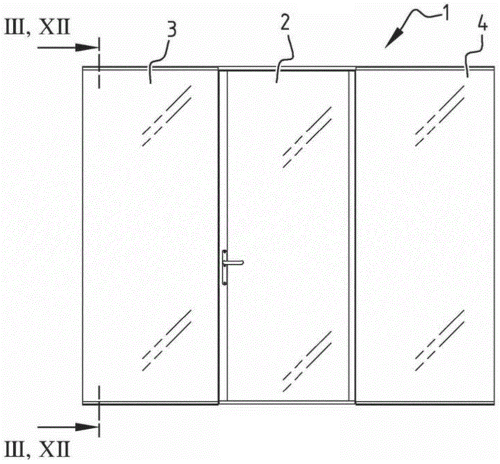
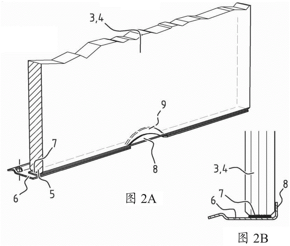
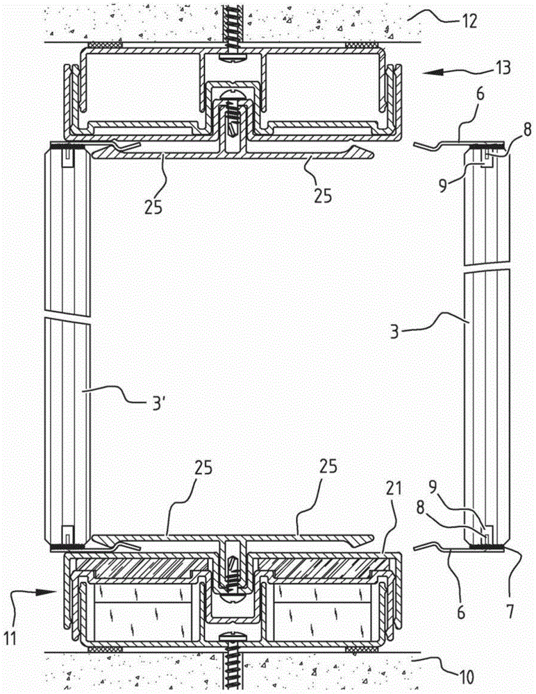
[0024] exist figure 1 In , a partition wall 1 designed for partitioning accessible spaces in a building is shown, made (for simplicity) of only one door 2 provided with glass panels 3 , 4 on both sides. As will still be explained below, each glass panel 3, 4 is provided at its bottom edge 5 with a lip 6 which extends inwardly (Fig. 2). The lip 6 extends along the entire width of the glass panel 3 , 4 and is fixed to the glass panel 3 , 4 via an adhesive strip 7 . The lip 6 is also flanged along part of its length, so that its flanged portion 8 protrudes into a corresponding shaped groove 9 ( FIG. 2 a ) of the glass pane 3 , 4 . It is pointed out that the glass panels 3, 4 are constructed in the same way on their upper sides, ie are also provided with a partially flanged lip 6, as image 3 shown. Figure 2b shows that the lip 6 is flanged along its entire length, the flanged edge 8 abutting the vertical side surfaces of the glass panels 3,4.

[0025] now refer to Figure 4 ...


PUM


Abstract

A wall comprising an upper horizontal member to be fixed to a ceiling, a lower horizontal member to be fixed to a floor, and at least one panel provided between the upper horizontal member and the lower horizontal member, characterised in that the lower horizontal member comprises at least two longitudinally extending, elongate profiles of U-shaped cross-section, wherein the first profile is fixed to the floor with a base part of its U-shaped cross-section, wherein the second profile is placed on the first profile, wherein base parts of the U-shaped cross-sections of the two profiles face away from each other, wherein the base part of the U-shaped cross- section of the second profile comprises a springy clamping profile mounted thereon, and wherein the panel comprises a lip fixed to its bottom edge, which lip extends inward and which is clampingly provided between the base part of the U-shaped cross-section of the second profile and the springy clamping profile so as to connect the panel to the lower horizontal member.

Description

technical field [0001] The invention relates to a wall comprising an upper horizontal member fixed to a ceiling, a lower horizontal member fixed to a floor, and at least one panel arranged between the upper horizontal member and the lower horizontal member. The invention relates in particular to such a wall which is or can be prefabricated from modular components. Background technique [0002] It is to be noted that, in the framework of the present invention, walls are partition walls specifically designed to separate accessible spaces in buildings. It is also to be noted that the panel according to the invention is preferably a glass panel or a panel of plastic material such as plexiglass. In other preferred variants, the panels are wood or steel panels. [0003] Such walls configured as partition walls are basically known. Known partition walls, also called "system walls", are used in various interior structures, for example in office buildings, airports, hospitals, ind...

Claims


Application Information

Patent Timeline
Patent Type & Authority Applications(China)
IPC IPC(8): E06B3/54E04B2/74E06B3/58E06B3/66
CPCE06B3/5821E04B2/745E04B2002/7462E04B2002/7496E06B3/5427E06B3/6621E04B2/825E04B2/7401E04B2/828
Inventor 约翰尼斯·约瑟夫夸克·旭昂·鲁彼得·马塞尔·德格拉夫
Owner MAARS HLDG BV
Features
  • R&D
  • Intellectual Property
  • Life Sciences
  • Materials
  • Tech Scout
  • Unparalleled Data Quality
  • Higher Quality Content
  • 60% Fewer Hallucinations
Learn More