High power linear constant current driving LED lamp module

A linear constant current drive, LED lamp module technology, applied in the direction of lamp circuit layout, lighting and heating equipment, point light source, etc., can solve the problem of large no-load power consumption, large change of full-load voltage, resistance-capacitance step-down drive scheme Instability and other issues, to achieve the effect of lossless

Inactive Publication Date: 2015-12-16
深圳市光科照明有限公司
View PDF4 Cites 2 Cited by
  • Summary
  • Abstract
  • Description
  • Claims
  • Application Information

AI Technical Summary

Problems solved by technology

At present, most of the high-voltage LED lamp modules on the market adopt the design of RC step-down drive scheme. The RC step-down drive scheme has unstable factors, and the safety cannot be guaranteed. In the no-load state, the full-load voltage changes greatly, which depends on The voltage regulator circuit bears the burden, resulting in large no-load power consumption, which is not conducive to energy saving and environmental protection, and is not isolated from the mains, and it is easy to burn the circuit when it is powered on.

Method used


Image

  • High power linear constant current driving LED lamp module
  • High power linear constant current driving LED lamp module
  • High power linear constant current driving LED lamp module

Examples


Embodiment Construction

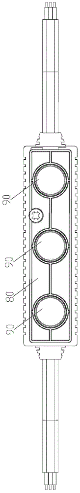
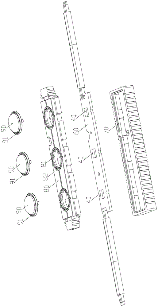
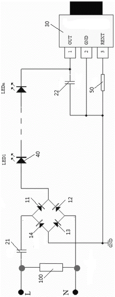
[0013] Such as figure 1 , 2 As shown in and 3, a high-power linear constant current driving LED lamp module provided in this embodiment includes a rectifier bridge 10, and the rectifier bridge 10 has a first diode 11 and a second diode 12 connected end to end. , the third diode 13 and the fourth diode 14, the fourth diode 14 and the first diode 11 have a first node, the first diode 11 and the second There is a second node between the diodes 12, a third node between the second diode 12 and the third diode 13, and the third diode 13 and the fourth diode There is a fourth node between the tubes 14, the third node is connected to the neutral wire terminal, and the fourth node is grounded; the step-down capacitor 21 is located between the live wire terminal and the first node; the linear constant A flow chip 30, the linear constant current chip 30 has a first connection terminal 31, a second connection terminal 32 and a third connection terminal 33, the second connection terminal...


PUM


Abstract

The invention provides a high power linear constant current driving LED lamp module with small pressure drop and low line loss, comprising a rectifier bridge provided with a first diode, a second diode, a third diode and a fourth diode which are connected end to end, wherein a first node is arranged between the fourth diode and the first diode; a second node is arranged between the first diode and the second diode; a third node is arranged between the second diode and the third diode; a fourth node is arranged between the third diode and the fourth diode; the third node is in connection with a zero line terminal; the fourth node is grounding; a buck capacitor located between a live wire terminal and the first node; a linear constant current chip provided with a first binding post, a second binding post and a third binding post, wherein the second binding post is in connection with the fourth node; LED beads located between the second node and the first binding post; an anti-surge capacitor located between the first binding post and the fourth node; and a constant current value adjusting resistor located between the third binding post and the fourth node.

Description

technical field [0001] The invention relates to the field of lamps, in particular to a high-power linear constant current drive LED lamp module. Background technique [0002] LED light, or light-emitting diode, is a solid-state semiconductor device that converts electrical energy into visible light. Due to its high luminous efficiency, it is more and more widely used in the field of advertising characters. At present, most of the high-voltage LED lamp modules on the market adopt the design of RC step-down drive scheme. The RC step-down drive scheme has unstable factors, and the safety cannot be guaranteed. In the no-load state, the full-load voltage changes greatly, which depends on The voltage regulator circuit bears the burden, resulting in large no-load power consumption, which is not conducive to energy saving and environmental protection, and is not isolated from the mains, and it is easy to burn the circuit when it is powered on. Contents of the invention [0003] T...

Claims


Application Information

Patent Timeline
IPC IPC(8): H05B37/02F21S2/00F21V17/16F21V19/00F21V23/02F21V31/00F21Y101/02
Inventor 袁武登彭伟孙建立刘安
Owner 深圳市光科照明有限公司
Why Eureka
Try Eureka