Electrical appliance

A technology for electrical equipment and power supply, which is applied to electrical components, circuit devices, emergency protection circuit devices, etc., and can solve problems such as pressure applied to electronic components

Active Publication Date: 2016-01-06
PANASONIC INTELLECTUAL PROPERTY MANAGEMENT CO LTD
View PDF9 Cites 0 Cited by
  • Summary
  • Abstract
  • Description
  • Claims
  • Application Information

AI Technical Summary

Problems solved by technology

[0003] However, conventional washing machines have a problem that a large surge current flows to the energization path every time the power outage is restored, putting pressure on the electronic components on the energization path.

Method used


Image

  • Electrical appliance
  • Electrical appliance
  • Electrical appliance

Examples


Embodiment approach 1

[0017] As an electric device, a washing machine will be described as an example.

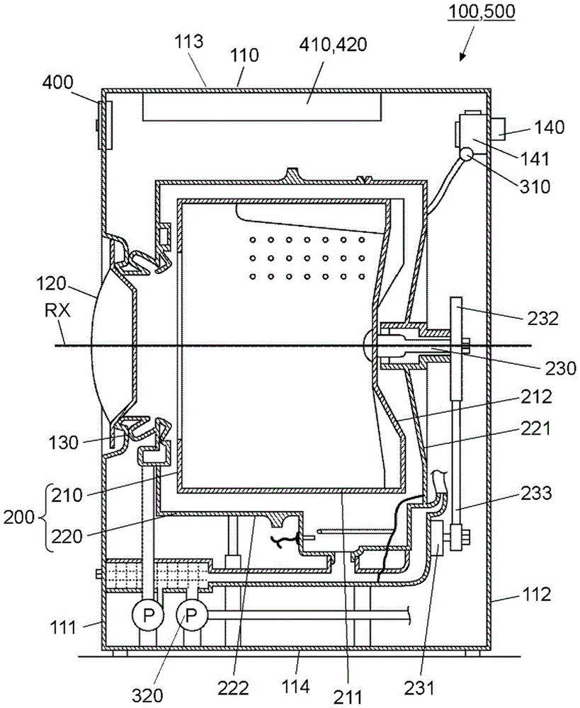
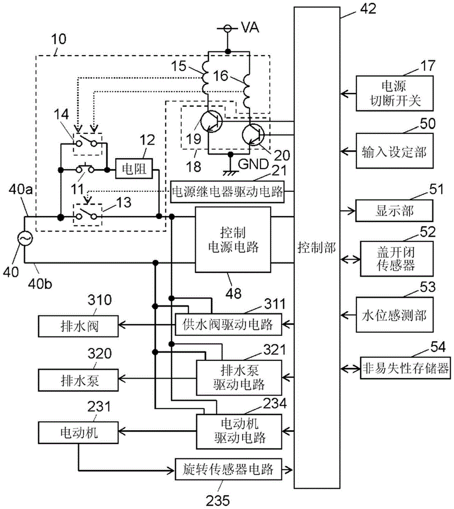
[0018] figure 1 It is a vertical cross-sectional view of a washing machine as an electric device according to Embodiment 1 of the present invention. figure 2 Is the control block diagram of the electrical equipment. In addition, the electric appliance is not limited to the washing machine 100, but may be, for example, a dryer, a dishwasher, or the like.

[0019] exist figure 1 Among them, the washing machine 100 includes a casing 110 and a storage tank 200 for accommodating laundry in the casing 110 . The storage tank 200 is equipped with the rotating drum 210 which has the substantially cylindrical peripheral wall 211 which surrounds the rotation axis RX, and the water tank 220 which accommodates the rotating drum 210. As shown in FIG.

[0020] The casing 110 has a front wall 111 and a rear wall 112 , wherein the front wall 111 is formed with an inlet for putting clothes into the storage t...

Embodiment approach 2

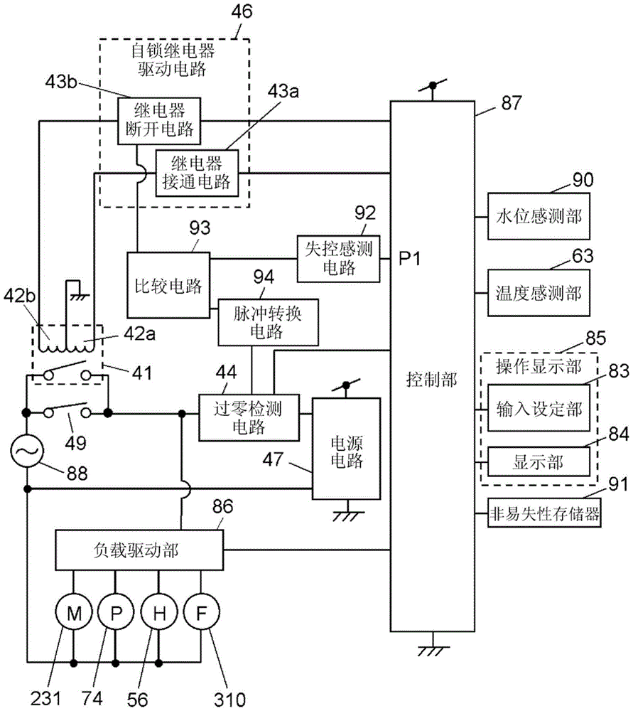
[0068] Next, use image 3 and Figure 4 Embodiment 2 of the present invention will be described. In addition, the components having the same configuration as those in Embodiment 1 are given the same reference numerals and their descriptions are omitted. Washing machine 500 of the present embodiment differs from washing machine 100 of Embodiment 1 in the configuration of control device 420 .

[0069] image 3 It is a control block diagram of the electric equipment in Embodiment 2 of this invention. Figure 4 It is a circuit diagram showing the details of a part of the control block diagram of the electric equipment.

[0070] The control unit 87 includes a microcomputer and the like. The control unit 87 receives the outputs of the water level sensing unit 90 for sensing the water level in the water tank 220 , the temperature sensing unit 63 , and the like. The control unit 87 displays the setting content on the display unit 84 based on the content set by the user inputting...

Embodiment approach 3

[0105] Next, use Figure 5 Embodiment 3 of the present invention will be described. In addition, the same code|symbol is attached|subjected to the component of the same structure as Embodiment 2, and description is abbreviate|omitted.

[0106] Figure 5 It is a control block diagram of the electric equipment in Embodiment 3 of this invention.

[0107] exist Figure 5 Among them, the ON signal cutoff circuit 45 is connected to the relay ON circuit 43 a and the comparison circuit 93 . The ON signal cutoff circuit 45 operates only when the comparison circuit 93 outputs "L", and stops the operation of the relay ON circuit 43a.

[0108] The structure other than the above structure is the same as that of Embodiment 2.

[0109] Next, the operation and function of the electric device configured as above will be described.

[0110] The operation in a state where the AC voltage from the commercial power supply 88 is supplied to the electric equipment and the control unit 87 loses ...


PUM


Abstract

An electrical appliance according to the present invention is provided with both a control unit (42), which performs a washing operation and receives power from a commercial power supply (40) through a control power supply unit (48), and a momentary power-on switch (11). The electrical appliance is also provided with a resistance (12) connected in series with the power-on switch (11), and a power supply relay (13) which is connected in parallel with the power-on switch (11) and the resistance (12) and which is turned on by operating the power-on switch (11). The electrical appliance is also provided with a latching relay (14) connected in parallel with the power-on switch (11) and in series with the resistance. Upon recovery from a power outage, power is supplied from the commercial power supply (40) to the control power supply unit (48) through the latching relay (14) and the resistance (12).

Description

technical field [0001] The present invention relates to electrical equipment such as a washing machine, a dryer, a dish washer, etc., which improve the start-up characteristics of a control device during recovery from a power outage to increase reliability. Background technique [0002] Among the conventional washing machines that take countermeasures against power failure and power restoration, there is a washing machine in which a switching device is provided in an energization path between a commercial power supply and a control power supply circuit. The energization path is closed by the user operating the switch device, and the closed state is maintained after the closing until the user gives an instruction to open it. Then, the energization path is disconnected based on the normal completion of the washing operation or the generation of a power cutoff command by the power cutoff command generating unit (for example, refer to Patent Document 1). [0003] However, the c...

Claims


Application Information

Patent Timeline
Patent Type & Authority Applications(China)
IPC IPC(8): G05B9/02D06F33/02D06F37/42H02H7/00D06F33/30D06F34/04D06F34/10D06F34/28
CPCD06F37/42H02H9/001D06F34/10D06F33/30D06F34/04D06F34/28G05B19/0428G05B2219/21169G05B2219/2633
Inventor 小川真理子高桥新
Owner PANASONIC INTELLECTUAL PROPERTY MANAGEMENT CO LTD
Why Eureka
Try Eureka