
Rotor assembly equipment and rotor assembly method

An assembly equipment and rotor assembly technology, which is applied in the manufacture of stator/rotor body, etc., can solve problems affecting rotor dynamic balance, demagnetization of magnetic steel, crushing magnetic steel, etc., to avoid demagnetization of magnetic steel, reduce scrap rate, and reduce heating The effect of temperature

Active Publication Date: 2018-07-24
GREE ELECTRIC APPLIANCES INC
View PDF7 Cites 0 Cited by
  • Summary
  • Abstract
  • Description
  • Claims
  • Application Information

AI Technical Summary

Problems solved by technology

[0004] 1. The shaft sleeve shrinks rapidly after being heated to high temperature, and there is a risk of the magnetic steel being compressed and damaged;
[0005] 2. The shaft sleeve shrinks quickly after being heated to high temperature, and there is an axial assembly gap between the parts, which affects the dynamic balance of the rotor when the rotor runs at high speed;
[0006] 3. When the shaft sleeve is hot-packed at high temperature, the high temperature will cause the magnet to demagnetize
[0007] 4. The pre-added axial load may crush the magnetic steel;

Method used


Image

  • Rotor assembly equipment and rotor assembly method
  • Rotor assembly equipment and rotor assembly method
  • Rotor assembly equipment and rotor assembly method

Examples


Embodiment Construction

[0039] The technical solutions in the embodiments will be clearly and completely described below in conjunction with the drawings in the embodiments of the present invention. Obviously, the described embodiments are only a part of the embodiments of the present invention, rather than all the embodiments. Based on the embodiments of the present invention, all other embodiments obtained by those of ordinary skill in the art without creative work fall within the protection scope of the present invention.

[0040] In the description of the present invention, it should be understood that the terms "center", "transverse", "longitudinal", "front", "rear", "left", "right", "upper", "lower", " The orientation or positional relationship indicated by "vertical", "horizontal", "top", "bottom", "inner", "outer" etc. is based on the orientation or positional relationship shown in the drawings, and is only for the convenience of describing the present invention and The description is simplifie...


PUM


Abstract

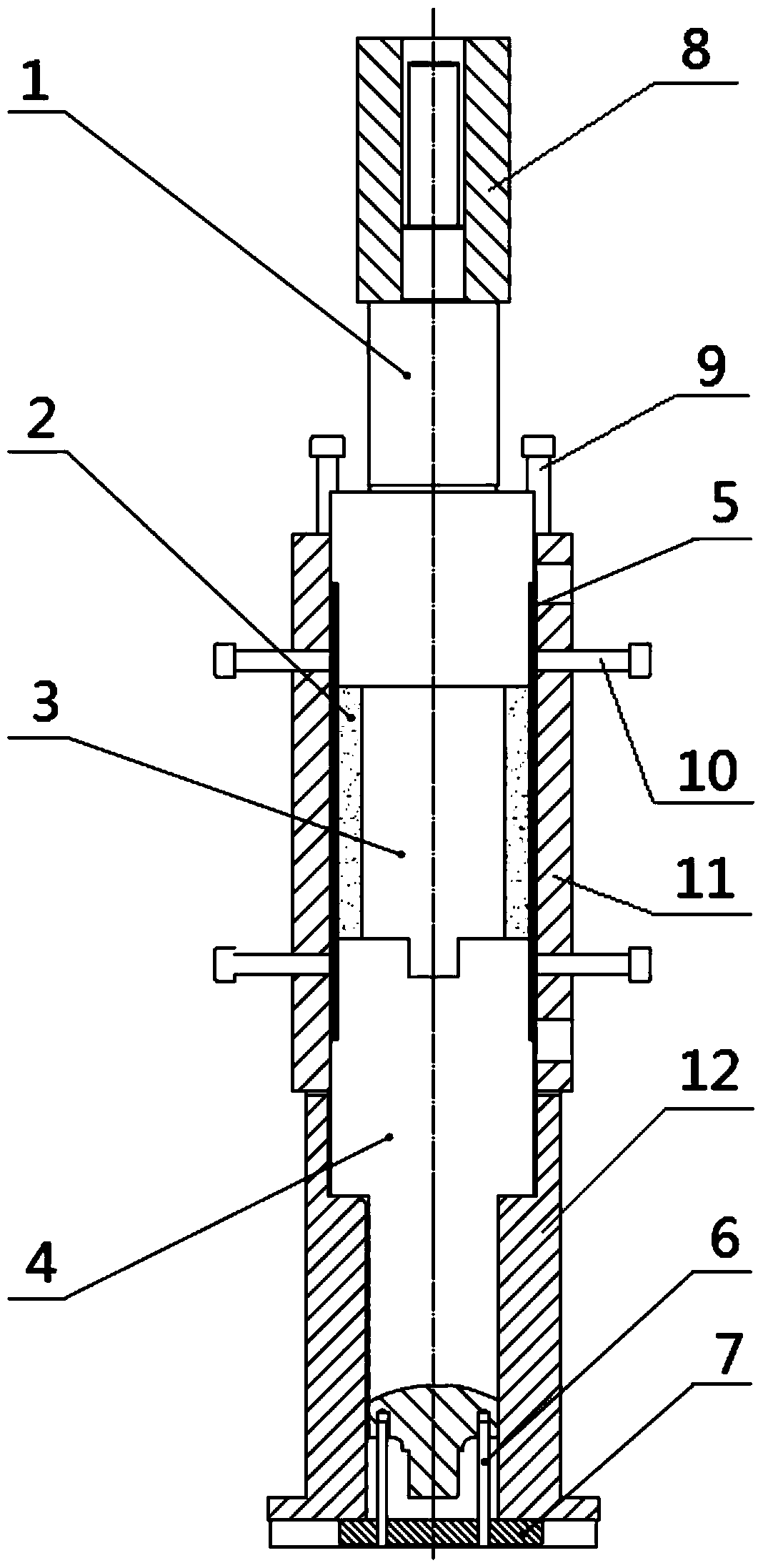
The invention relates to assembly equipment for a rotor and a rotor assembly method. According to the assembly equipment for the rotor, the rotor comprises a sheath (5), and magnetic steel (2) can be mounted in the sheath (5); the assembly equipment for the rotor comprises a heat insulating lantern ring (11); the periphery of the sheath (5) is sleeved with the heat insulating lantern ring (11) so that heat of the sheath (5) can be preserved in the process of heating the sheath (5) before mounting the magnetic steel (2) in the sheath (5). Through arrangement of the heat insulating lantern ring used for preserving heat of the heated sheath, the maximum heating temperature of the sheath can be maintained, the hot charging time of the sheath can be prolonged, quick chilling shrinkage of the sheath can be avoided, the risk of damaging the magnetic steel due to compression is lowered, and the problem that a large axial clearance exists between parts and influences dynamic balancing of the rotor is avoided; with respect to the same hot charging time, the initial heating temperature of the sheath can be lowered, superhigh temperature operation is avoided, and then demagnetization of the magnetic steel due to a high temperature is avoided; the success rate of assembly is improved, and the rejection rate is lowered.

Description

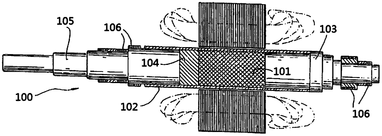
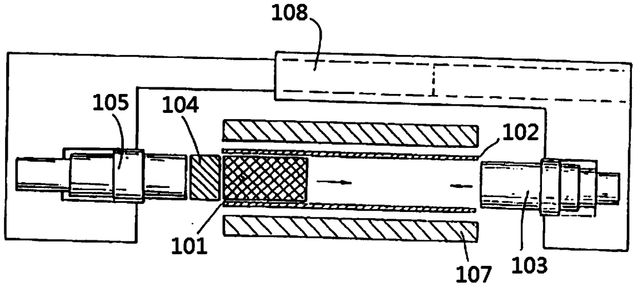
Technical field [0001] The invention relates to the technical field of rotor assembly, in particular to an assembly equipment for a rotor and a rotor assembly method. Background technique [0002] High-speed machines have high requirements on the mechanical properties of the rotor. At present, there is a rotor for high-speed machines in the prior art, which has a structure such as figure 1 , figure 2 As shown, the rotor 100 is used by a high-speed brushless DC motor to drive a centrifugal compressor, and is composed of a magnet 101, a shaft sleeve 102, a non-magnetic shaft section 103, a spacer 104, a magnetic shaft section 105, and a magnetic bearing 106. When assembling, the heater 107 heats the sleeve 102 to 400℃~480℃, and then uses the shaking tool 108 to insert the magnetic steel 101, the non-magnetic shaft section 103, the spacer 104 and the magnetic shaft section 105, and the shaft sleeve 102 is rapidly cooled , Even when the sleeve 102 shrinks around the outer surface o...

Claims


Application Information

Patent Timeline
Patent Type & Authority Patents(China)
IPC IPC(8): H02K15/02
Inventor 张芳刘健宁龚高郭长光贾金信李广海田思园
Owner GREE ELECTRIC APPLIANCES INC
Learn More