Rough machining method for partspan shroud of turbine blade

A turbine blade and boss technology is applied in the field of rough machining of turbine blade damping bosses. Effect

Active Publication Date: 2016-02-03
DONGFANG TURBINE CO LTD
View PDF4 Cites 2 Cited by
  • Summary
  • Abstract
  • Description
  • Claims
  • Application Information

AI Technical Summary

Problems solved by technology

In order to process all the damping bosses, the traditional method needs to be carried out from several different angles. Because of the problem of empty knife and knife connection, the processing efficiency is very low, and the area between the blade profile and the damping boss is unavoidable. There is full cutting, resulting in large cutting force, large tool consumption, resulting in deformation of the blade, and cannot leave a uniform margin for finishing

Method used


Image

  • Rough machining method for partspan shroud of turbine blade
  • Rough machining method for partspan shroud of turbine blade
  • Rough machining method for partspan shroud of turbine blade

Examples


Embodiment Construction

[0026] In order to describe the technical features and functions of the present invention in detail and realize them according to the content of this specification, the implementation of the present invention will be further described below in conjunction with the accompanying drawings.

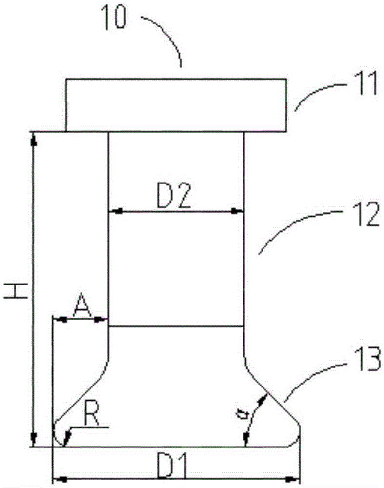
[0027] figure 1 An embodiment of a tool 10 according to the invention is schematically shown. Such as figure 1 As shown, the tool 10 includes a tool handle 11 , a tool bar 12 and a tool head 13 . Among them, H is the overhang length of the tool, which should be greater than the maximum distance from the top of the damping boss to the steam channel profile, D1 is the maximum working diameter of the cutting edge, D2 is the diameter of the tool bar 12, and the tip R is determined by the blade. The selection principle It is advisable not to be larger than the rounded corner of the blade processing part. The A value is the radius difference between the cutter head 13 and the cutter bar 12. When ...


PUM


Abstract

The present invention discloses a rough machining method for a partspan shroud of a turbine blade. The method comprises the following steps: (1) selecting a cutter which has a radius difference between a cutter bit and a cutter bar equal or greater than the depth of the reversing shaded side of the partspan shroud to be machined; and (2) creating a numerical control machining procedure of the partspan shroud according to the features of the partspan shroud and the selected cutter, and by controlling the gesture of the cutter, machining the sharp curved surface of the partspan shroud and the adapter position of the partspan shroud and the root of the blade profile by a chamfer of the cutter, where the small position of the cutter bar of the cutter avoids the interference part of the shaded side of the partspan shroud. The method uses a cutter to finish the rough machining of the profile and the bottom of the partspan shroud, makes margin for finish machining, and improves the machining quality. It does not need to replace the cutter and does not need supplemental machining. The ineffective cutting time (except feeding and relieving) is short. The load of the machine tool is uniform, and the cutting process is smooth. Therefore, the machining efficiency is greatly improved, and the difficulty and bottleneck of the shroud machining is efficiently overcome.

Description

technical field [0001] The invention relates to the field of turbine blade processing, in particular to a rough machining method for a damping boss of a turbine blade. technical background [0002] The damping boss of the turbine blade is a space convex curved surface on the inner back arc surface at the proper position of the steam channel height of the turbine blade, and the turbine blade profile is a complex curved and twisted space surface. In order to improve the shock absorption characteristics and enhance the working strength, the large blades are generally of a structure with a damping boss. [0003] The machining of turbine blade damping boss has always been the difficulty and bottleneck of blade machining. When CNC machining blades, the 3+2 method is usually used for rough machining. With the optimization of the design, the parameters of the turbine unit are getting higher and higher, and the damping boss becomes more and more complex, generally a complex space s...

Claims


Application Information

Patent Timeline
Patent Type & Authority Applications(China)
IPC IPC(8): B23P15/02
CPCB23P15/02
Inventor 梁鹏李启山王龙清李启元熊小聪廖龙胥家良
Owner DONGFANG TURBINE CO LTD
Why Eureka
Try Eureka